
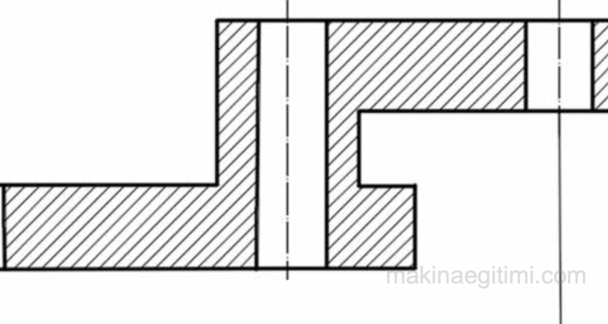
Hatching lines in technical drawing
If a part can be introduced more clearly by taking a section through it, we draw it as a section instead of a plain view.
Sectional views are especially used in places where we need to see the shape of the part’s interior more clearly.
When drawing a section, the part is assumed to have been cut with a saw, and the cutting plane usually passes through the axis. The portion of the part in front of this plane is assumed to be removed, and the view of the remaining rear portion is drawn. The areas where the saw touched the part are filled with equally spaced, thin lines at a 45° angle. This is called hatching.
Open spaces in the part that the saw did not touch are not hatched.
How are hatching lines done in technical drawing
Hatching in technical drawing follows certain standards, and the rules of hatching in technical drawing are listed item by item below.
1- Hatching lines are drawn as thin, parallel lines at a 45° angle to the part’s axis, evenly spaced, sloping either to the right or to the left. The spacing between these lines varies depending on the size of the surface being hatched.

2- On a solid (single-piece) part, the hatching direction is the same throughout. However, in assembly drawings, the hatching of adjoining parts is done in opposite directions.

3- Rather than hatching very small surfaces, it is more suitable to fill them in solid black.

4- When the edges of the surfaces to be hatched are at a 45° angle to the horizontal plane, hatching is done as shown below.

5- We said that when defining sectioning, we assume the part was cut with a saw. However, in longitudinal sections, solid parts such as shafts, bolts, and rivets are normally not hatched, even where the saw would have touched them.

6- Reinforcing ribs appear as though they were cut, but they are not hatched in a sectional drawing.

7- Chains, on the other hand, are hatched as shown below.

8- Structural profile sections with small hatching surfaces are, as seen in the example below, filled in solid black, separated from one another by white lines.

9 – The figure below shows a bushing sectioned along its full length. In shapes like this, showing the section from a single view is sufficient. There is no need for a sectional view from the side.

10 – Sometimes parts too long to fit on the paper, such as shafts, pipes, etc., need to be shown as though broken off at some point. Sections shown as broken off are represented as below.


This article was about hatching lines in technical drawing . Here we tried to provide the basic information on the topic. For more extensive and detailed information and hatching examples, and sectional drawing examples, you can check the RELATED TOPICS section shown below.
Related Posts
 Technical Drawing View Extraction Examples 2
 International Projection Standards ISO-E and ISO-A
 Specifying the Manufacturing Method by Surface Roughness
 Auxiliary Views in Technical Drawing
 Geometric Drawings 2 – Dividing Circles
 Form and Position Tolerances in Technical Drawing
 Tolerance Terms and Their Meanings in Mechanical Engineering
 Hole and Shaft Tolerances