Close Menu
  • MAKİNELER ve İMALAT
    • Tools & Equipment
    • Computer-Aided Drawing
    • CAD/CAM Education
    • CNC Machine Programming
    • Casting Technologies
    • Electrical & Electronics Technologies
    • Hydraulics & Pneumatics
    • Manufacturing Processes
    • Manufacturing Technologies
    • Occupational Safety
    • Mold & Die Design
    • Solid Modeling
    • Welding Technology
    • Machine Elements
    • Mechanical Trade Drawing
    • Materials Science
    • Automotive & Vehicle Technologies
    • Robotics Technologies
    • Health Technologies
    • Defense & Aerospace Technologies
    • Descriptive Geometry
    • Technical Drawing
    • Software & Hardware Technologies
    • Innovative Manufacturing Methods
  • TEKNOLOJİ ve YAŞAM
    • OTOMOBİLLER ve TAŞIT
      • Vehicle & Engine Knowledge
      • Safe Driving
      • Sürüş Destek Sistemleri
    • Genel Kültür
      • Movies & TV Shows
      • Görsel ve Grafik Sanat
      • Books & Literature
      • Music
      • Sports
      • History
      • History of Technology
    • GÜNDELİK YAŞAM TEKNOLOJİLERİ
    • Hobbies & Entertainment
    • Internet Technologies
    • Health
    • Mobile Technologies
Makine Eğitimi
  • Machines & Manufacturing
    Machine Elements
    Hydraulics & Pneumatics
    Technical Drawing
    Computer-Aided Design & Manufacturing
    Basic Manufacturing Processes
    Manufacturing Processes
    Industry Technologies
    Other Technical Courses
    Motion & Power Transmission
    Simple Machines
    Chains & Sprockets
    Shafts & Journals
    Gears
    Cams
    Couplings
    Belts & Pulleys
    Springs
    Bearings
    Keys
    Fastening Joining
    Retaining Rings
    Screws, Bolts & Nuts
    Cotter Pins
    Flanges
    Welding
    Rivets
    Pins & Bolts
    Washers
    Calculators
    Gear Ratio Calculator
    Spring Constant Calculator
    Belt Pulley Ratio Calculator
    Other Machine Elements
    Slides & Linear Guides
    Brakes
    Flywheels
    Clamps
    Shock Absorbers
    Gaskets & O-Rings
    Seals & Sealing Elements
    Hydraulics
    Introduction to Hydraulics & Principles
    Hydraulic Systems & Applications
    Accumulators
    Filters
    Motors
    Pumps
    Valves
    Pneumatics
    Introduction to Pneumatics & Principles
    Pneumatic Systems & Applications
    Pneumatic Circuit Components
    Valves
    Cylinders
    Silencers
    Motors
    Compressors
    Dryers
    Conditioning Units
    Common Topics & Maintenance
    Hydraulic & Pneumatic Maintenance
    Study Notes, Exams & Tests
    Technical Drawing
    Introduction to Technical Drawing
    Geometric Drawings
    Perspective & Projection
    Orthographic Views
    Dimensioning
    Sectioning
    Assembly & Detail Drawings
    Tolerances
    Surface Finish Symbols
    Mechanical Engineering Drawing
    Screws, Bolts & Nuts
    Pulley Drawings
    Gear Drawings
    Shafts & Journals
    Bearing Drawings
    Pins & Bolts
    Spring Drawings
    Welds in Technical Drawing
    Washers
    Cotter Pins
    Technical Drawing Exercises
    Mechanical Drawing Exercises
    Gear Exercises
    View Extraction Exercises
    Pulley Exercises
    Pin & Bolt Exercises
    Threaded Fastening Exercises
    Descriptive Geometry
    Computer-Aided Drawing
    AutoCAD Drawing Lessons
    Solid Modeling & Animation
    Solid Model Drawing Files
    Solid Model Assembly Examples
    Solid Model Drawing Lessons
    3D CAD Software Reviews
    Solid Modeling Exercises
    CNC Programming
    CAM
    Measurement & Inspection
    Dial Indicators
    Calipers
    Gauges
    Micrometers
    Materials Science
    Steels
    Cast Iron
    Aluminum
    Plastics
    Material Testing & Hardness Measurement
    Occupational Safety
    Workshop Safety
    Safety When Working With Electricity
    Machine Safety Rules
    Hand Operations
    Filing
    Marking
    Cutting Operations
    Reaming
    Tapping
    Threading With a Die
    Drill Bit Sharpening
    Working With Machines
    Basic Turning Operations
    Basic Milling Operations
    Shaper Machine
    Machining
    Turning
    Milling
    Grinding
    Innovative Manufacturing Methods
    EDM (Electrical Discharge Machining)
    Laser Machining
    Waterjet Machining
    3D Printing
    3D Scanners
    Welding
    Rolling
    Casting
    Mold & Die Design
    Mechanical & Hydraulic Presses
    Blanking & Piercing Dies
    Bending Dies
    Drawing Dies
    Plastic Injection Molds
    Extrusion Dies
    Compound Dies
    Progressive Dies
    Blow Molds
    Spinning Dies
    Spray Molds
    Manufacturing of Machine Parts
    Automotive & Vehicle Technologies
    Motor Vehicle Manufacturing
    Raw Material Production
    History of Technology
    Health & Medical Technologies
    Defense & Aerospace
    Robotics Technologies
    Software & Hardware Technologies
    Mechanics - Strength of Materials
    Physics Topics
  • Technology & Life
    Hobbies & Entertainment
    Sports
    Music
    Vehicle & Engine Knowledge
    Vehicle Maintenance & Repair
    Safe Driving
    Driver Assistance Systems
    History
    Movies & TV Shows
    Books & Literature
    Computers & Internet
    Computer Tips
    Software Reviews
    Hardware & Peripherals
    Practical & Safe Internet Use
    Visual & Graphic Art
    Mobile Technologies
    Travel
    Science
    Health
    First Aid Knowledge
    Everyday Technologies
Makine Eğitimi
Home»Manufacturing Processes»What Is Marking? What Are the Marking Tools?
29 August 2026

What Is Marking? What Are the Marking Tools?

About Marking

What is marking? 

Basic manufacturing processes are among the introductory topics in machining. The process of drawing the relevant part drawing onto the actual workpiece, with the correct features, is called marking (layout) . The purpose of marking is to create the marks and lines that allow machine parts to be machined in accordance with the part drawing. It ensures that workpieces are machined accurately and easily.

  • What is marking? 
  • Marking (Layout) Tools
    • Marking (surface) plate
    • V-blocks
    • Steel Rulers
    • Number/Letter Stamps
    • Scribers
    • Height Gauges
    • Dividers
    • Prick Punch / Center Punch
    • Bevel Protractor
    • Hammer
    • Centering Square
    • Centering Bell
    • Marking (Layout) Dyes
  • How is marking done?
  • Related Questions

Importance of the Reference Surface


Before starting the marking process, a proper reference surface must be established to ensure accurate measurements.

Use of Marking (Layout) Fluid


Marking (layout) fluid applied to metal surfaces makes the scribed lines appear more clearly.

Role of the Center Punch


The center punch marks the points where holes are to be drilled, preventing the drill bit from wandering off center.

Marking (Layout) Tools

  • Surface plate,
  • V-blocks,
  • Steel rulers,
  • Number/letter stamps
  • Scribers,
  • Height gauges,
  • Dividers,
  • Center/prick punch,
  • Hammers,
  • Centering square,
  • Centering bell,
  • Marking (layout) dyes,
  • How Is Marking Done?

Marking (surface) plate

These are tables or slabs made of ribbed cast iron with flat working surfaces on which marking is carried out.

marking (surface) plate

Since the surface must remain flat for marking to be accurate, operations such as drilling, cutting, punching, or hammering are not carried out on the surface plate. Any action that could damage the surface plate is avoided.

V-blocks

V-block with cylindrical part

V-blocks are generally used to make marking cylindrical parts easier. Because of their weight, they can also be used as a support during the marking process.

Steel Rulers

steel ruler

Besides being used for measuring during marking, rulers are also used to draw straight marking lines on workpieces. The steel ruler is one of the most commonly used marking tools.

Number/Letter Stamps

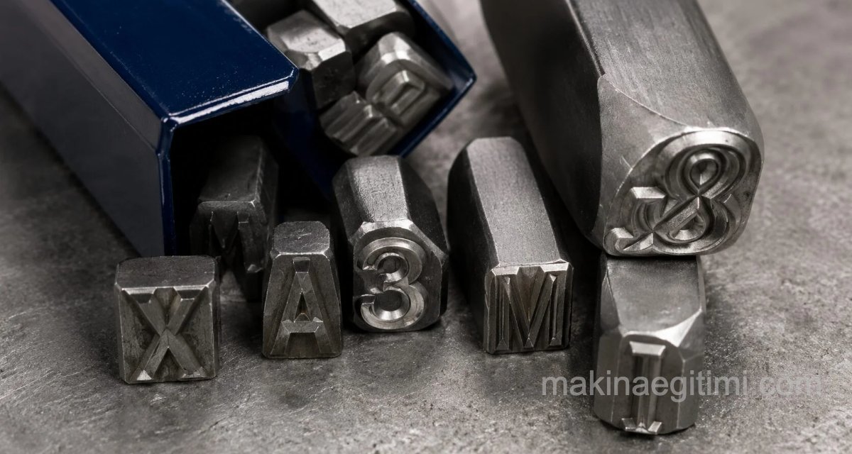
Number/letter stamps are hardened metal bars with a number or letter formed on one end. By striking them with a hammer, they are used to punch a permanent number or lettering onto metal workpieces.

Scribers

Scribers are used to draw lines on metal surfaces during marking. Their bodies are made of soft steel, while their tips are made of alloy steel or diamond and hard-brazed onto the body. Tip angles range from 10 to 30 degrees. Scribers should not be carried in apron pockets and should not be used as a prick punch.

Height Gauges

Height gauges are used to draw parallel lines at a desired dimension during marking. They are one of the most important marking tools. There are simple vernier and precision (digital) indicator versions of height gauges.

height gauge
Simple vernier and precision indicator height gauges

NOTE: For a sample workpiece marking example on the use of a height gauge, see:
SEE ALSO: Clamping Shoe Exercise Manufacturing Stages

Dividers

Dividers are used to draw circular lines during marking. Pressure should be applied on the pivot (center) leg of the dividers. If pressure is applied on the scribing leg instead, the dividers will slip. 

steel dividers
Steel dividers used in marking

To use dividers on a hole, the hole is filled with a wooden plug.

Prick Punch / Center Punch

The prick punch: used to make small dents so that marking lines are not lost and to determine the centers of holes to be drilled, and also to guide the drill bit. It is made of chrome or vanadium steel.

prick punch marking tool
Prick punch

There are two types of punches. One is the center punch, prepared to guide the drill into holes (with a tip angle of 90 degrees). The other is the prick punch, used so that marking lines are not lost during work and to mark edge lines. Its tip angle is 60 degrees.

When striking the punch, it is first held at an angle so the marking lines can be seen. It is then straightened upright and struck with a hammer.

using the prick punch in marking
Preparing and striking the punch

The punch marks should not deviate from the centerline of the marking lines. Punch marks should be struck close together on curved lines and spaced farther apart on straight lines.

An additional control circle should also be drawn for precise marking of holes. The control circle serves to show whether the hole being drilled will be centered or not.

clamping shoe drawing and workpiece
the role of punch marks in marking

In the sample workpiece above, the areas where holes are to be drilled have been marked with punch marks, which serve to guide the drill bit into position.

Bevel Protractor

steel bevel protractor
A steel bevel protractor is used both in marking and for checking drill bit point angles.

Hammer

A hammer is a striking tool made of steel with both ends hardened. It is used in weights of 50, 75, 100, 150, 200, 250, 300, 400, and 500 grams.

Centering Square

Centering square: used to draw lines passing through the center of cylindrical parts.

centering square
using a centering square

Centering Bell

Centering bell: used to determine the centers of cylindrical parts from their face surfaces.

centering bell
centering bell

Marking (Layout) Dyes

A marking dye is chosen based on the properties of the surface. Coating a surface with dye makes the marking lines easier to see.

marking dye copper sulfate

Copper sulfate powder, also known as “bluestone” in manufacturing, is used as a marking dye. Copper sulfate is normally blue in color. When mixed with water and applied to a metal surface, it produces a reddish-brown (copper-colored) finish.

ready-made commercial marking dye

Ready-made marking dyes are also available for purchase. Thanks to properties such as fast drying, protecting the metal from rust, and being unaffected by oil, these dyes are especially suitable for die and mold makers. They must be stored carefully, as they are flammable.

How is marking done?

Order of Operations in Marking: 

  • Any burrs on the workpiece are removed,
  • Surfaces to be marked are coated with marking dye,
  • The workpiece is placed on the surface plate,
  • Axes and centers are drawn first and marked with the punch,
  • The drawing is then transferred onto the part,
  • The marking is checked.
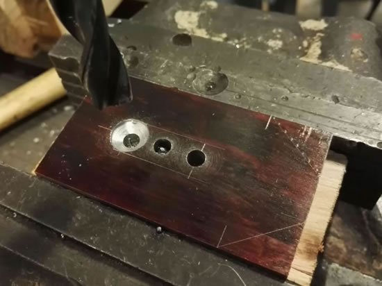
drilling the clamping shoe workpiece on a drill press

On the clamping shoe workpiece, the area where a hole is to be drilled and an elliptical channel is to be formed has been marked out with marking lines and punch marks. Likewise, the angled section visible on the right side of the part has also had its boundaries defined with marking lines.

Copper sulfate (bluestone), mixed with water and used for marking purposes, colors iron and steel objects copper-colored when applied to their surface

Copper sulfate (bluestone) is used for coating cleaned steel surfaces. Bluestone colors the surfaces copper.


In this article, we defined marking. We examined marking tools. We explained how marking is done.

Related Questions

Lines drawn on a bright metal surface can sometimes be hard to see. Marking fluid creates a dark background on the surface, making the lines drawn on it much more visible and easier to read.

On an unmarked surface, the drill bit can easily wander away from the intended point as drilling begins. The small dent made by the center punch fixes the drill bit at the correct point and prevents this wandering.

Related Posts
Workplace Safety When Working With an Angle Grinder Workplace Safety When Working With an Angle Grinder Work Instructions at a Drill Press Work Instructions at a Drill Press MENGENE ÇEŞİTLERİ KONU ANLATIMI Types of Vises, Lesson Reamer Hole Tolerance Table Reamer Hole Tolerance Table What Is Riveting. How Is It Done? What Is Riveting. How Is It Done? Torna Aynası Nasıl Sökülür Takılır. How to Remove and Install a Lathe Chuck Frezede Güvenli Çalışma Kuralları Safe Working Rules on a Milling Machine 1/20 (0.05) Caliper Reading Online Test 1/20 Caliper Reading Online Test
Hand Operations Marking
Share. Facebook Twitter WhatsApp Tumblr Email Telegram Copy Link

Leave A Reply Cancel Reply

Lionel Messi’s Legendary Body Feints
Traffic Regulatory Signs and Their Meanings. Restriction and Command Signs
  • Contact
  • Terms of Service
  • Privacy & Cookie Policy

Type above and press Enter to search. Press Esc to cancel.