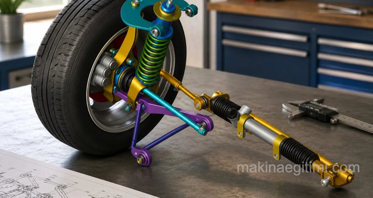
On our pages of SolidWorks assembly examples that can support your mechanical engineering lessons, we’ve dedicated this publication to the vehicle suspension system and its detail drawings. It also contains detail drawings you can use in your mechanical technical drawing and CAD/CAM work. The files are provided in formats that can be opened in SolidWorks.
Suspension System
The job of the suspension system is to absorb (damp) the energy generated by road bumps, rough surfaces, and speed bumps, vehicle body motion, and the centrifugal force in turns, and to transmit as little of it as possible to the chassis.

The suspension system, positioned between the vehicle body and the wheels, is designed to damp the vibrations caused by the road surface. The suspension system is needed for both ride comfort and safety. The suspension system works as an integrated whole with the steering system, front-end geometry, and the wheels.
The suspension system has two basic jobs. The first is driving safety, the second is ride comfort. In the suspension system, shocks and vibrations from the road are absorbed by the springs, while the shock absorbers damp the spring’s oscillation. This is how vehicle comfort is achieved.
The suspension system also improves the vehicle’s road holding by keeping the wheels in maximum contact with the road under all road and driving conditions, and by counteracting the dynamic forces acting on the vehicle.

Elements of the Suspension System:
- Springs: Take on the shocks coming from the road.
- Shock absorbers: Provide ride comfort by damping the springs’ oscillations.
- Sway bar (anti-roll bar): Prevents the vehicle’s lateral roll.
- Linkage system: Connects all the parts of the suspension system to each other in a coordinated way, controlling the wheels’ longitudinal and lateral movement.
Now that we’ve given some general information about the suspension system, let’s move on to the download links for the solid-modeling assembly work whose drawings we’ve included in this article.

Vehicle suspension
download the SolidWorks solid-modeling assembly drawing
vehicle suspension solid modeling, assembly drawing download
Suspension System 2
Another example of a SW assembly project. This one includes both wheels, so the linkage system is easier to understand. The download link is provided below as a zip file.
The part assembly drawings are provided along with the solid model part drawings. The solid modeling was done in SolidWorks.

SW assembly examples
download suspension system 2
Related Posts