
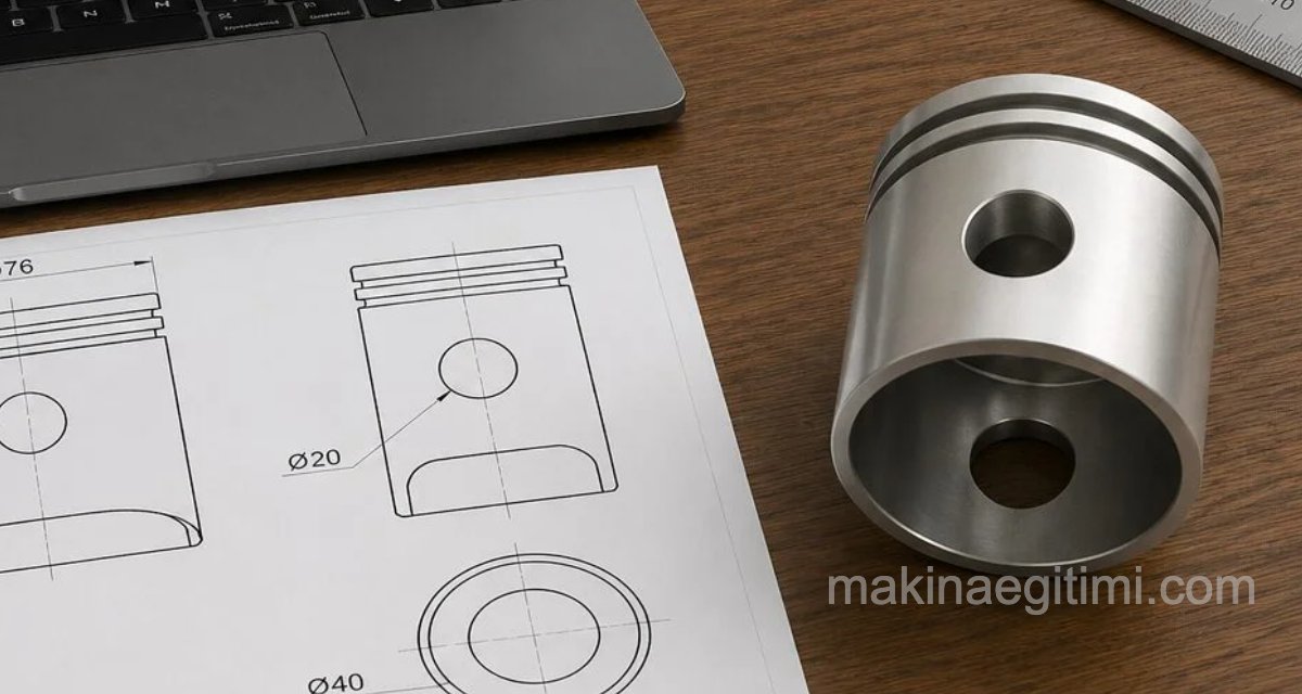
SolidWorks video and illustrated tutorial. The Revolve, Shell, and Extruded Cut commands are used. This is one of the exercises that can be useful for your SolidWorks solid modeling practice.
Technical drawing of the part shown in the video: VIEW and DOWNLOAD PDF (Turkish document)
Video Tutorial
Illustrated Tutorial

We start by opening a sketch on the front plane. We create the drawing shown above. The dimensions may differ, but for the shape to look correct, the proportions between the dimensions should be as shown.

Next, we run the Revolved Boss/Base command from the Features tab.
If the dynamic menu on the left asks for a revolve axis, we select the axis line shown in the image above.
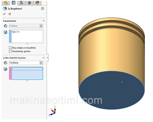
Next, we look at our solid model from below, select the bottom face, and choose the SHELL command from the Features menu. In the dynamic menu on the left, we set the wall thickness to 2 mm.

Next, we open a sketch on the RIGHT PLANE and draw a circle centered exactly in the middle, as shown above. Diameter 35 mm.
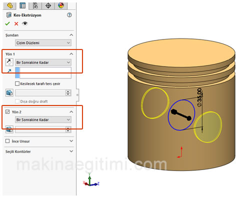
Next, we run the EXTRUDED CUT command from the Features menu. Since the circle we drew is created in the middle of the solid model, we will apply the command in both directions. The areas shown with a red rectangle in the image above.
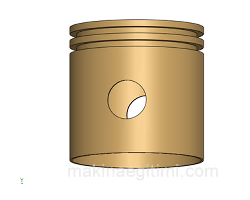
If everything has gone well, our solid model is complete and should look like the image above. If you get stuck on any details, watch the video.
Related Posts
 AutoCAD Solid Model Examples
  What Is SLDPRT, How Do You Open an SLDPRT File?
  Download SolidWorks Assembly Examples
 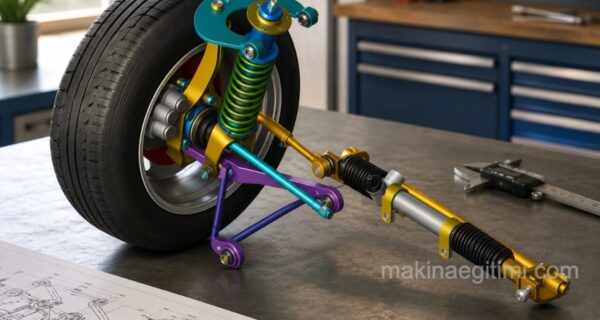 SolidWorks Assembly Examples – Suspension System
  SolidWorks Splined Shaft Drawing – Tutorial and Files
 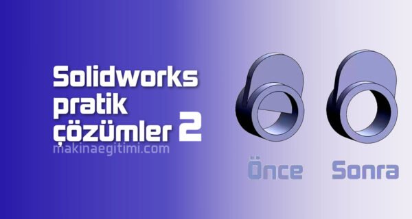 SolidWorks Practical Solutions and Tips-2
  SolidWorks Solid Model Exercise-8 / Sweep
 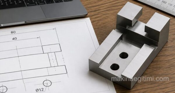 SolidWorks Sample Solid Model Drawing -3 / Video + Document