

In hydraulic systems, the entire circuit doesn’t always need to operate at the same pressure. While a system’s main line may run at high pressure, a branch circuit connected to that line may need to operate at a much lower pressure. This is exactly where the pressure reducing valve comes in. In this article, we’ll go step by step through what this valve does, how it works, and what types exist.
What Is a Pressure Reducing Valve?
In hydraulic systems, a single pump is generally selected based on the highest pressure demand in the system. However, some parts of the system may require a lower, constant pressure. This is where pressure reducing valves (pressure regulator valves) come into play.
A pressure reducing valve is a pressure control component that keeps the pressure at the valve’s outlet at a preset constant value, independent of the main line pressure. No matter how high the system pressure rises, the pressure at the valve outlet does not exceed the set value.
What Does a Pressure Reducing Valve Do?
In a hydraulic system, different actuators (cylinders, motors, etc.) may need to operate at different pressure levels. For example, in a press machine, the main compression line may require high pressure, while an auxiliary clamping circuit in the same system may only need a much lower pressure. A pressure reducing valve makes it possible to obtain multiple pressure levels from a single pump in such situations. This provides the following benefits:
- Circuits with different pressure requirements can be fed from a single hydraulic power unit.
- Equipment requiring low pressure is not damaged by exposure to excessive pressure.
- Energy efficiency and circuit safety in the system are improved.

Summary of the diagram above:
- Main circuit: High pressure from the pump (e.g., 250 bar) goes directly to the main press cylinder. The pressing operation that requires high force is performed here.
- Auxiliary circuit: Branched off the main line via a pressure reducing valve and set to a lower pressure (e.g., 80 bar). This pressure feeds the auxiliary cylinders (clamping, pusher, holder, etc.).
- In this way, two different pressure levels are provided by the same pump; energy efficiency increases, and the auxiliary components are not exposed to excessive pressure.
Operating Principle
Pressure reducing valves are normally open. The operating logic is as follows:
- The pressure on the outlet (secondary) side of the valve acts against the spring force.
- When the outlet pressure reaches the set value, the valve partially closes, creating a pressure drop between the inlet and outlet.
- This keeps the outlet pressure constant.
- When fluid consumption on the outlet side increases, the valve opens further; when consumption decreases, it throttles down.
In short: the inlet pressure (primary) can vary, while the outlet pressure (secondary) remains constant.
Types of Pressure Reducing Valves
Based on their control method, pressure reducing valves are examined in two main groups.
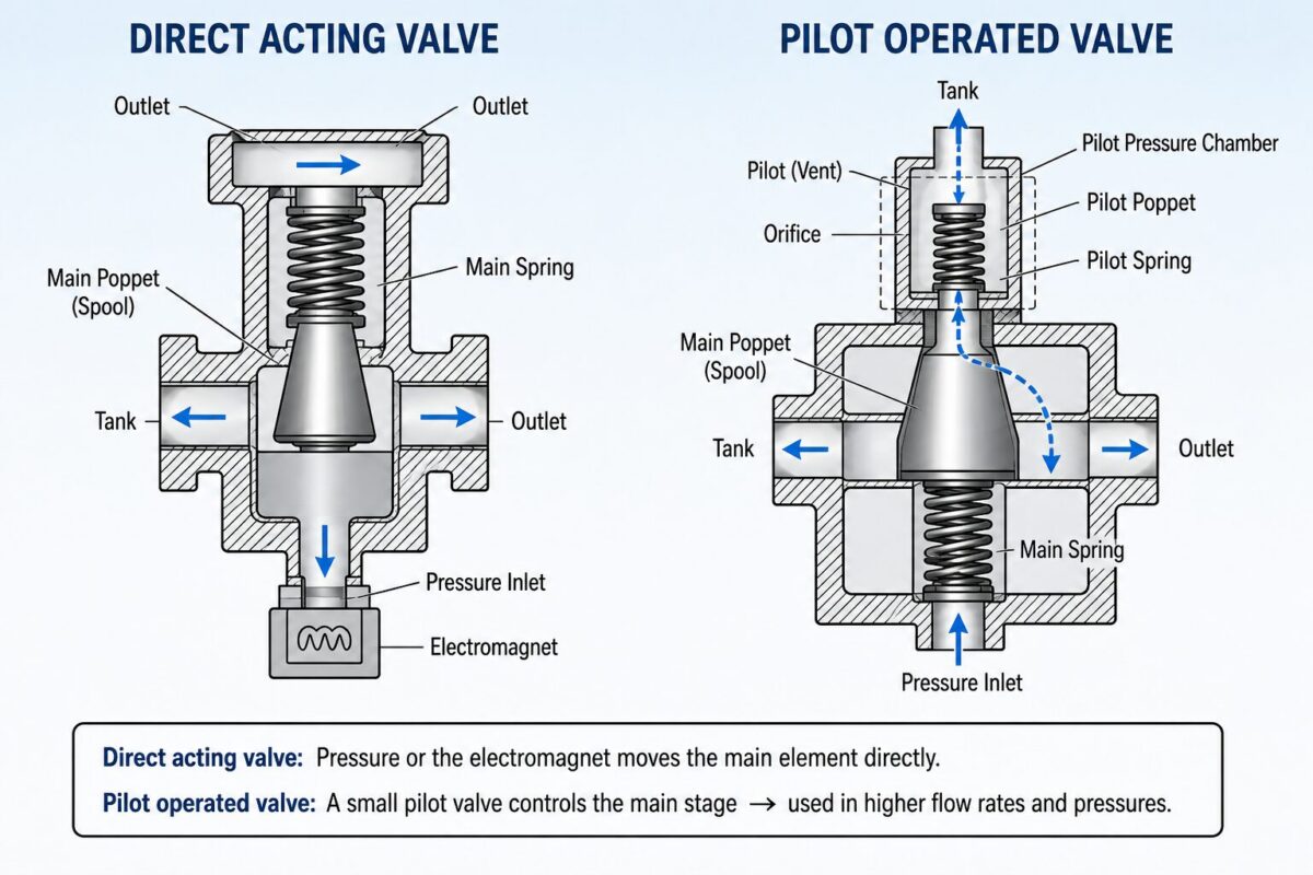
Direct-Acting Pressure Reducing Valve
In this type, the outlet pressure acts directly on the valve’s spool, and the force moving the spool is balanced by a spring. Because of its simple structure, it is preferred in low- and medium-flow systems. However, at high flow rates, the required spring force becomes very large, reducing adjustment precision.
Pilot-Operated Pressure Reducing Valve
In high-flow systems, a small pilot valve controls the main spool. The pilot valve acts like the system’s measuring element, sensing small changes in outlet pressure and governing the movement of the main spool. This design provides precise and stable pressure control even in high-flow circuits. This type is generally preferred in large-scale industrial hydraulic systems.
3-Way and 2-Way Types
2-way pressure reducing valves have only inlet and outlet connections and cannot return the excess flow generated during pressure balancing back to the tank line; this can cause pressure fluctuations in some circuits. 3-way types include an additional tank connection; when the outlet pressure exceeds the set value, the valve discharges the excess flow directly to the tank, providing more stable and faster pressure regulation. 3-way types are generally preferred in precision positioning or clamping applications.
The Difference Between a Pressure Reducing Valve and a Pressure Relief Valve
These two valves are components that technical school students frequently confuse. Their fundamental differences can be summarized as follows:
| Feature | Pressure Reducing Valve | Pressure Relief Valve |
|---|---|---|
| Normal position | Open | Closed |
| Pressure it acts on | Outlet (system) pressure | Inlet (pump) pressure |
| Role in the circuit | Part of normal function | Safety component |
| Function | Continuous pressure regulation | Emergency relief |
| Purpose of use | Providing low pressure in sub-circuits | Protecting the system from excessive pressure |
| Flow | Provides continuous flow | Only opens under excessive pressure |
Areas of Use
Pressure reducing valves appear in almost every hydraulic system that requires more than one pressure level:
- Operating different functions at different pressures in mobile hydraulics (construction equipment).
- Precision positioning cylinders in pneumatic and hydraulic control systems on industrial automation lines. Low pressure requirements independent of the main line.
- In press machines, operating clamping, holding, or pushing cylinders at lower pressure while the main circuit runs at high pressure.
- Feeding clamping circuits in machine tools at a low pressure independent of the main system. Part clamping circuits — low, constant pressure to prevent over-clamping.
- Brake circuits (mobile hydraulics) — controlled and constant brake pressure
- Providing dedicated pressure to each actuator in systems with multiple actuators

Example Circuit Scenario
Let’s consider a concrete example: in a sheet metal press, suppose the main hydraulic power unit operates at 250 bar to feed the large press cylinder. The same machine has a clamping cylinder that holds the sheet metal steady before pressing, and this cylinder needs to operate at only 40-50 bar so as not to damage the material.
If this cylinder were connected directly to the main line, the 250 bar pressure could crush the material or overload the clamping mechanism. At this point, a 3-way pressure reducing valve reduces the 250 bar from the main line to a constant 45 bar specific to the clamping circuit; even if the main line pressure fluctuates during production (for example, between 230-260 bar), the pressure in the clamping circuit continues to stay steady at around 45 bar.
This scenario illustrates in concrete terms why the pressure reducing valve is indispensable in practice. During the design phase, it should be clearly determined which sub-circuits require low, constant pressure, and a pressure reducing valve of appropriate capacity (in terms of flow rate and pressure range) should be selected for those circuits; a valve with insufficient capacity may fail to provide the flow rate the circuit demands, causing loss of speed or a drop in pressure.
Advantages
- Ability to obtain multiple pressure levels from a single pump
- Energy savings (low-pressure circuits don’t unnecessarily operate at high pressure)
- Prevention of actuators and hoses being exposed to excessive pressure.
- Longer system lifespan and less heat generation
Evaluation in Terms of Energy Efficiency
While pressure reducing valves are functionally necessary, they are not entirely loss-free in terms of energy; since they reduce excess pressure by throttling it, some energy is lost as it converts to heat.
In system design, if the flow rate of the circuit requiring low pressure is large, using a separate, low-pressure second pump (dual-pump system) instead of feeding it from a single pump through a pressure reducing valve can be more advantageous in terms of energy efficiency.
For low-flow, occasionally used circuits, however, using a pressure reducing valve remains both more economical and more practical than investing in an additional pump.
Points to Consider During Installation and Use
- The valve’s drain line (in pilot-type valves) must always be connected to the tank. If this line is blocked, the valve will not function properly.
- Turning the adjustment screw clockwise generally increases the pressure.
- The valve should be mounted as close as possible to the actuator it protects.
- Filtration quality is important; dirty oil can damage the valve’s precision components.
- The set pressure must be below the system’s pressure relief valve setting.
Fault Symptoms and Maintenance
One of the most common problems with pressure reducing valves is the failure of the outlet pressure to remain stable at the set value. The main causes of this include wear between the spool and the body, blockages caused by contaminated hydraulic oil, and spring fatigue.
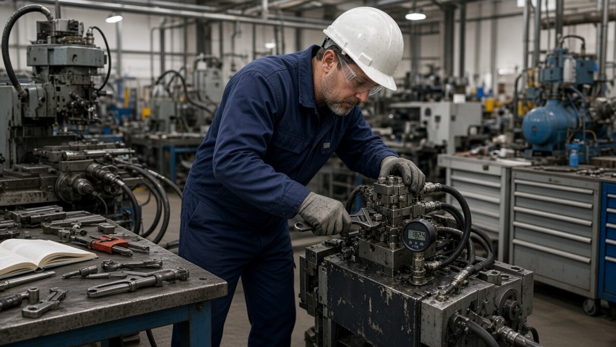
Pressure reducing valve adjustment is generally done using an adjustment screw on the valve or via electronic proportional control; during adjustment, the actual pressure should be monitored with a pressure gauge connected to the outlet line.
When the valve malfunctions (spool sticking, spring breakage, blockage due to contamination), the sub-circuit may be exposed to higher pressure than expected; this can cause damage to connected components, part deformation due to over-clamping, or a safety risk.
Sudden and unexplained pressure fluctuations are usually the first sign of contamination buildup inside the valve. Regular oil filtration and periodic valve inspection are the most effective ways to prevent this type of failure.
Conclusion
Pressure reducing valves are indispensable components of modern hydraulic systems. Especially in press, injection molding, and machine tool applications that require multiple pressure levels, they provide both energy efficiency and system safety.
A correctly selected and correctly adjusted pressure reducing valve significantly improves both the performance and lifespan of the system.
Frequently Asked Questions
A pressure reducing valve is open in its normal position; when the outlet pressure reaches the set value, it throttles the flow to keep the pressure constant.
No. A pressure relief valve is normally closed and protects the system from excessive pressure, while a pressure reducing valve is normally open and continuously regulates the outlet pressure of a sub-circuit.
Pilot-operated pressure reducing valves are preferred in high-flow systems, where direct-acting valves cannot provide sufficient precision.
It is widely used in hydraulic systems that require multiple pressure levels, such as press machines, machine tools, construction equipment, and industrial automation lines.
The most common problem is the outlet pressure failing to remain stable at the set value, due to contaminated hydraulic oil or wear.
Yes, since it reduces excess pressure by throttling it, some energy is lost as heat; for high-flow, low-pressure circuits, using a separate pump may be more efficient.
The desired outlet pressure is generally set using an adjustment screw on the valve or via electronic proportional control; during adjustment, the actual pressure should be monitored with a pressure gauge connected to the outlet line.
The sub-circuit may be exposed to higher pressure than expected; this can cause damage to connected components, part deformation, or a safety risk.
Related Posts
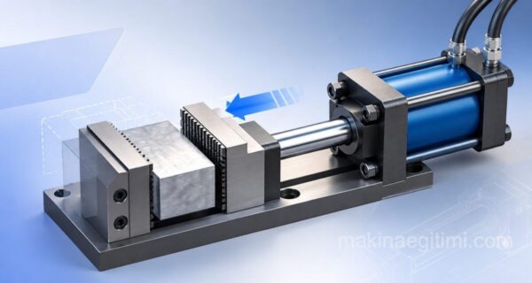 Hydraulic Applications – Clamping Fixture
 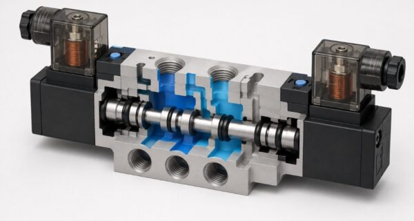 What Is a Solenoid Valve, How Does It Work?
  AND Valve Explanation and Applications
  Introduction to Pneumatics and Definitions
  Reciprocating Compressor | Working Principle, Parts, Types
  4-Way 2-Position Directional Control Valves
  Hydraulic Filter Selection
  An Overview of How Pneumatic Systems Work