Machine technology hydraulics/pneumatics lecture notes / Time delay valve explanation and applications. A topic explanation enriched with example circuit diagrams and example applications
What Is a Time Delay Valve
It consists of a pneumatically piloted 3/2 directional control valve, a check valve, and a small compressed-air reservoir.
Normally Closed Time Delay Valve
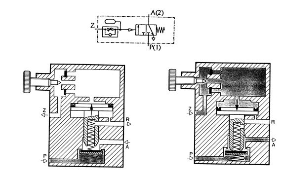
Pilot air (Z) passes through the adjustable restrictor into the reservoir, building up pressure there. This pressure acts on the pilot piston. It pushes the pilot piston down, opening the passage from (P) to (A) and shutting off airflow from A to R. Purpose: this valve is used when the Z-start signal needs to take effect only after a certain time.
APPLICATION-1

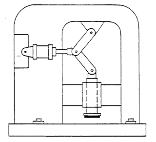
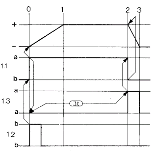
In the timing circuit, signal element 1.2 is triggered very briefly, changing the direction of setting element 1.1 and extending the piston rod. At the same time, a switching pulse from the pressurized working line enters the time delay valve. It passes through the adjustable one-way flow control valve, and at the end of the set time, it opens the 3/2 directional control valve inside the timing valve, delivering compressed air out through working line 2 (A). This compressed air returns pilot valve 1.1 to its initial position, causing the piston to retract.
In the timing circuit, signal element 1.2 is triggered very briefly, changing the direction of setting element 1.1 and extending the piston rod. At the same time, a switching pulse from the pressurized working line enters the time delay valve. It passes through the adjustable one-way flow control valve, and at the end of the set time, it opens the 3/2 directional control valve inside the timing valve, delivering compressed air out through working line 2 (A). This compressed air returns pilot valve 1.1 to its initial position, causing the piston to retract.
APPLICATION-2
Plastic workpieces will be stamped with the help of a press. For safety, the stamp will move forward only when two buttons are pressed at the same time. Once it reaches the end position, the stamping pressure will act on the workpiece for 20 seconds. Afterward, the stamp will return to its starting position.
- Identify the circuit symbols.
- Prepare the circuit diagram.
- Which physical quantity (pressure, restrictor cross-section, or air volume) affects the time delay

B-Normally Open Time Delay Valve

Compressed air arriving via Z acts on the pilot piston. The valve spool shuts off airflow from P to A. As the pressure acting on the piston increases, airflow from A to R is enabled. For the valve to return, the Z-pilot line must be connected to exhaust. The pilot air is released through the check valve. Airflow from A to R is shut off, and then airflow from P to A opens.
The delay is achieved with a fixed restrictor and an adjustable compressed-air reservoir
Limit Switch (Roller-Actuated) Delay Valve

Condition: Initially, limit switch 1.8 (roller-actuated) is engaged (piston rod pressed against it)
When valve 1.2 or 1.4 is triggered briefly, the output from valve (1.6) goes to the output of valve 1.10. (If 1.8 is not initially engaged, it does not go — there is an AND condition) and it triggers valve 1.1 (via signal line 14), changing its position; the cylinder extends and 1.8 becomes disengaged. The piston extends and touches limit switch 1.3, actuating it. Valve 1.3 triggers valve 1.1, changing its position, and the piston moves to the retracted position. 1.8 becomes engaged again. The control system is now back in its starting position.
Application-3
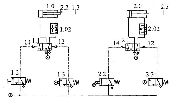

The hinged roller-lever valve is passed over without being actuated (initially). Cylinder 1.0 is triggered just before reaching its rearward end position, causing valve 2.1 to change position.
Application-4

APPLICATION-5
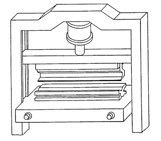
Punch presses, guillotine shears, and similar machines carry a significant accident risk. To prevent these accident risks, two-hand controls equipped with timing behavior have been developed as complete assembly units. Two-hand controls require both signal elements to be triggered simultaneously within 0.5 seconds. Number the assembly elements. Identify the valve connections. Complete the circuit diagram by drawing the logic symbols. What are the consequences of swapping the two logic elements with each other? Does this circuit have memory? What is the function of the memory? Explain the signal flow:
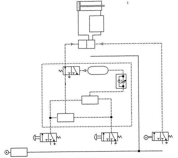
a) When signal elements 1.2 and 1.4 are pressed simultaneously.
b) When only signal element 1.2 is triggered, and
c) When signal element 1.2 is triggered first, and then, after a 2-second interval, signal element 1.4 is triggered.
Related Posts