
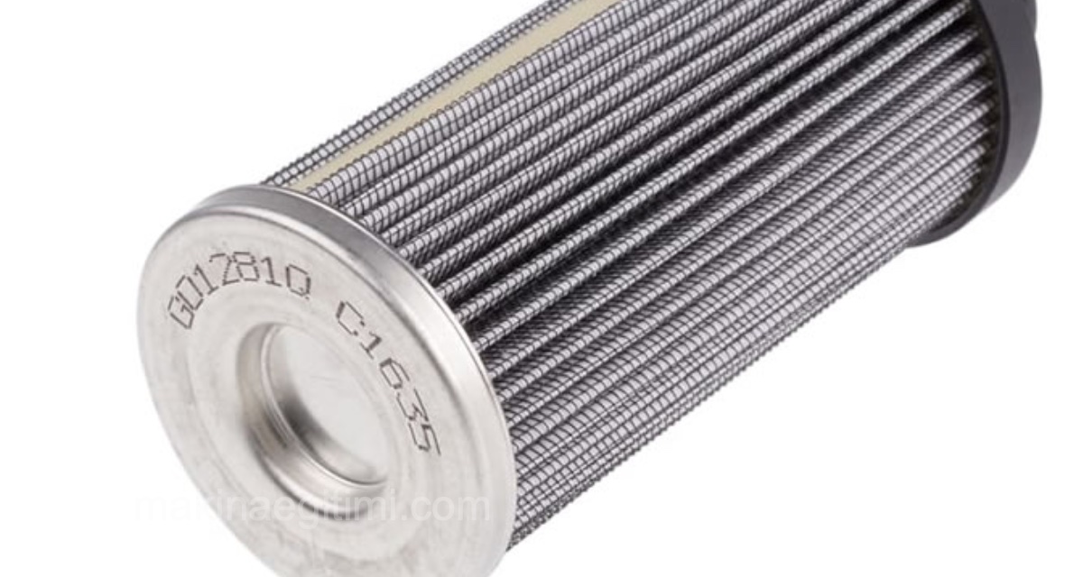
In our Hydraulics and Pneumatics lecture notes, in the section covering components of hydraulic systems, we’ve dedicated this post to filter selection in hydraulic systems. How and on what basis should hydraulic filter selection be made? What are the criteria? We’ll focus on this.
Hydraulic filter selection is an important topic for hydraulic systems. A quality filter is important for the stable operation, low maintenance cost, and long service life of a hydraulic system. For this reason, there are some properties that need to be considered when selecting a hydraulic filter.
Hydraulic Filter Selection Criteria

Every filter causes some amount of pressure loss. The following values are recommended for this:
Filtering the main flow:
Pressure line filter Δp – 1 to 1.5 bar at operating temperature
Return line filter Δp – up to 0.5 bar at operating temperature
Suction line filter Δp – 0.005 to 0.1 bar at operating temperature.
Filter Selection for Filtering the Secondary (Kidney-Loop) Flow
The secondary flow pump’s flow rate should be approximately 10% of the fluid volume specified for the tank.
To keep pressure losses low, the filter should be selected sufficiently large. The viscosity factor f, and the pressure loss Δp caused by the housing and filter element, are provided by the manufacturer.
The total pressure difference for the filter is calculated using the formula:
Δp_total = Δp_housing + f . Δp_element

Filtration Ratio
Hydraulic filters typically have a particle-capture capacity of between 3-25 microns, depending on the application.
Pressure Drop Control
When selecting a filter, it’s important to choose the right pore size so it doesn’t cause an excessive drop in system pressure.
Role of the Bypass Valve
The bypass valve that activates when the filter clogs protects the pump by preventing the system from running dry.
Step-by-Step Hydraulic Filter Selection
Step 1:
Determining the Target Cleanliness Level (or Micron Rating)
When selecting a hydraulic filter, you should always identify which component in the system is the most sensitive. Then you should choose the filtration cleanliness level or micron rating for that component. In most cases, this could be a variable piston pump or a proportional valve. The table below is a simple chart to help you determine what your ISO code should be for your most critical components.


Using this chart, we now know the minimum ISO cleanliness level our system needs to maintain for proper operation. Once we’ve determined our ISO code, we can look at filter manufacturers’ catalogs. For this example, we’ll use Schroeder Industries, considered one of the leaders in mobile hydraulic filtration.

As you can see, for example, if you’re using a closed-loop hydraulic system with a variable piston pump and proportional control valves, we need an 18/16/13 ISO cleanliness level. According to the chart published by Schroeder, this would be a Z5 filter media (5 microns).
We’ve determined the media or micron rating of the filter we’ll use. Now, we’ll select what type of filter to use. For example, a pressure filter, a suction filter, or a return line filter.
Step 2: Targeting the Cleanliness Level
Another important point in hydraulic filter selection is achieving the required target cleanliness level. There are generally 4 important factors in positioning contamination control devices within a hydraulic system.
1- Initial filter element efficiency
2- Filter element efficiency under system stress
3- The location and size of contamination control devices in the system
4- Filter element service life
While all of these items are important, filter manufacturers (Schroeder, Parker, Eaton, Hydac) typically design their filters to have the highest element efficiency in the industry, so we’ll focus only on the last two items: the proper location and sizing of your filter. Done correctly, this will provide the best service life for your system.
Step 3: Selecting the Correct Filter Type (or Location)
In the example we gave earlier, Schroeder Industries carries hundreds of different filter types. For hydraulic filter selection, you first need to look at the type of filters you want: suction, pressure, and return-line filtration can be your options.
Suction filters are generally the “large-particle (rags, etc.) catchers” you put in your tank, meant to filter out bolts or rags that might fall into the reservoir. However, they’re generally not used to filter fluids.
Pressure filters are recommended for placement downstream of your pump. If your pump “vomits” or fails, all downstream flow components still need to be protected. These filters must always be rated for your system’s operating pressure and ISO code.
Return line filters are important because they clean the oil before it “returns” to the hydraulic reservoir, so if you’re only going to use this type of filter, you need to keep your reservoir clean. Return line filters are generally used in open-loop applications and should be rated to the ISO code your system requires.
While all three filter types aren’t needed in the same system, it’s important that every application has at least one pressure filter or one return line filter, to maintain the fluid cleanliness level required by the hydraulic components. Please see the table below, prepared by Eaton (Vickers) to help with your selection.

Note: Click the image to view a larger version.
Step 4: Selecting the Correct Filter Size (or Pressure Drop)
Once you’ve determined what type of filter you want to use, for hydraulic filter selection, you need to consider the pressure drop across the filter. In most cases, pressure filters and return filters include a “bypass” that protects the system when the filter clogs. It allows the system to keep running by letting the oil bypass the filter element unfiltered. We know that in this situation, your system is running unfiltered.
As your filter becomes dirty, it requires more pressure to “push” the oil through the element. Once this pressure reaches a certain point, the system becomes inefficient and you waste power in the hydraulic system; this is the reason for the bypass system. Typically, bypass settings on pressure filters are 40-50 PSI, to limit this inefficiency.
When sizing a pressure filter, we generally want to keep the pressure drop across the filter under 10 PSI. This is because it gives your filter more time before reaching the 50 PSI bypass setting, thereby increasing the time between element changes. If you size your filter with a 25 PSI pressure drop, you’re already at “half” of the filter’s life (assuming a 50 PSI bypass). If we choose a filter with only a 10 PSI pressure drop, your filter will have a 40 PSI pressure drop before it reaches the bypass setting, allowing the element to last much longer without needing service.
Another thing to consider is oil viscosity. Thicker oil (oil with higher viscosity) causes a higher pressure drop, so you need to consider which oil will run in your system in order to properly size the filter and get the best filter life for your application.
Properties of a Good, Quality Hydraulic Filter
What should a good hydraulic filter be like? Although the answer to this question depends on the hydraulic filter’s intended use, hydraulic filter selection in general comes down to whether the filter meets the following criteria:
A good hydraulic filter should show stability against pressure differences.
It should have β stability across a wide pressure range.
It should have filtering power for all cleanliness grade classes.
The hydraulic filter should have high dirt-holding capacity even under high pressure.
The hydraulic filter should have a large filter area.
The hydraulic filter should have a long service life.
It should have an appropriate price-to-performance ratio.
In this article, we covered how and on what basis hydraulic filter selection should be made. We looked at points to consider in hydraulic filter selection and what to watch for when choosing a hydraulic filter. We hope you found it useful.
Related Questions
Every filter offers some resistance to the passage of fluid, which causes a pressure loss in the system. Since too large a pressure loss would reduce the system’s efficiency, this loss must be kept within acceptable limits when selecting a filter.
A larger filter surface causes less pressure loss at the same flow rate. This allows the system to be cleaned continuously and efficiently without unnecessarily straining the secondary flow pump.
Related Posts
 Types of Pneumatic Compressors
 Pressure Reducing Valve: Working Principle, Types, and Applications
 OR Valve Explanation and Applications
 Hydraulic Filtration Arrangements
 What Is a Hydraulic Flow Divider? What Does It Do?
 Screw Compressors: Construction, Types, Strengths, and Weaknesses
 Pneumatic Directional Control Valves
 Force Calculations in Pneumatic Cylinders