

In this article, under our hydraulics-pneumatics category, we’ll look at the systems of machines that incorporate hydraulic systems in certain areas of industry, such as machine tools. We’ll cover topics like hydraulic system applications in machine tools, the hydraulic system on a shaper, a shaper’s hydraulic circuit diagram, hydraulic planers, a planer’s hydraulic circuit, a grinding machine’s hydraulic circuit, and how a hydraulic milling machine operates.
Hydraulic systems being cheaper than other options, easier and safer to maintain and repair, and allowing speed and direction to be controlled as desired, is what’s allowed them to be used in place of mechanical systems. Their compatibility with programmable control systems has also helped hydraulic systems take hold and spread throughout industry. Nearly all the machines used in the machinery industry, and some of their attachments, have been converted to run on hydraulic systems, finding widespread application in industry.
Hydraulic Shaper
As is known, on a shaper, the cutting tool moves linearly back and forth, machining the workpiece fixed to the table.
On hydraulic shapers, the motion is created by the fluid pressurized by the hydraulic pump, converted into linear motion in a single-acting hydraulic cylinder. As a result, the cutting tool (tool bit) attached to the cylinder’s piston rod moves linearly.
The Hydraulic System on a Shaper
The operating system of a hydraulic shaper is a good example of hydraulic system applications in machine tools.
Fluid from the hydraulic pump passes through the relief valve at a set pressure value and enters the directional control valve. The fluid selected by the directional control valve enters the cylinder and pushes the piston forward (+). The cutting tool (tool bit) attached to the piston rod moves forward, cutting. The shaper’s stroke is set using stops.
When the cutting tool reaches the end of its stroke, the directional control valve’s control lever strikes a stop and the valve’s position changes. When the directional control valve’s position changes, the piston and the cutting tool attached to the piston rod move backward (-).
Since the shaper’s hydraulic cylinder is single-rod, the machine’s forward stroke is slow and its return stroke is faster. This is because the fluid coming from the same pump fills the piston-rod side of the hydraulic cylinder faster than the other side.

Hydraulic Planer
Planers and grinding machines, used in the metal-cutting manufacturing industry, are similar to each other as systems. The difference between a planer and a shaper is that on a planer, the cutting tool is fixed and the workpiece moves. For this reason, planers are used to machine heavier and larger-sized parts.
On planers, the hydraulic cylinder that moves the machine’s table is a double-acting cylinder. Since a planer’s table is large and heavy, and heavy loads are clamped to it, the hydraulic system needs a more powerful pump and a larger-capacity oil reservoir.

On a hydraulic planer, the machine’s table moves by means of two double-rod hydraulic cylinders. The pressurized fluid the hydraulic pump sends into the hydraulic system moves the double-acting cylinder’s piston forward, and with it the machine’s table. When the piston moves backward, the machine’s table also moves backward. On double-rod cylinders, piston speed is equal in both directions.
If the work clamped to the machine’s table is being cut as the table moves forward, it may be desirable for the table to return faster. In this case, or whenever the table’s speed needs to be set to a desired amount in either direction, speed is adjusted by fitting flow control valves. Since a planer’s table has a long stroke, the hydraulic cylinders used here are also long.
Because a planer’s worktable and the work clamped to it are large and heavy, moving the table is done using two large-capacity hydraulic cylinders. The cylinders’ forward and backward motion happens simultaneously. The hydraulic cylinders on a planer can be controlled by the same directional control valve, or by separate directional control valves. The flow and pressure control valves in the circuit allow the fluid’s pressure and the machine table’s speed to be controlled.
Hydraulic Grinding Machine
Grinding machines are among the most precise machines used in the metal-cutting manufacturing industry. For this reason, grinding machines need to run quietly and without vibration. This is why nearly all grinding machines built to date run on hydraulic systems.
On grinding machines, hydraulic systems are used for the table’s back-and-forth motion, for advancing and retracting the wheel relative to the work, and for clamping the work between two centers. All of this is achieved by the fluid pumped by the hydraulic pump connected to the same hydraulic system, distributed and controlled through various hydraulic circuit components. We’ll look at the linear left-right motion of a hydraulic grinding machine’s table.
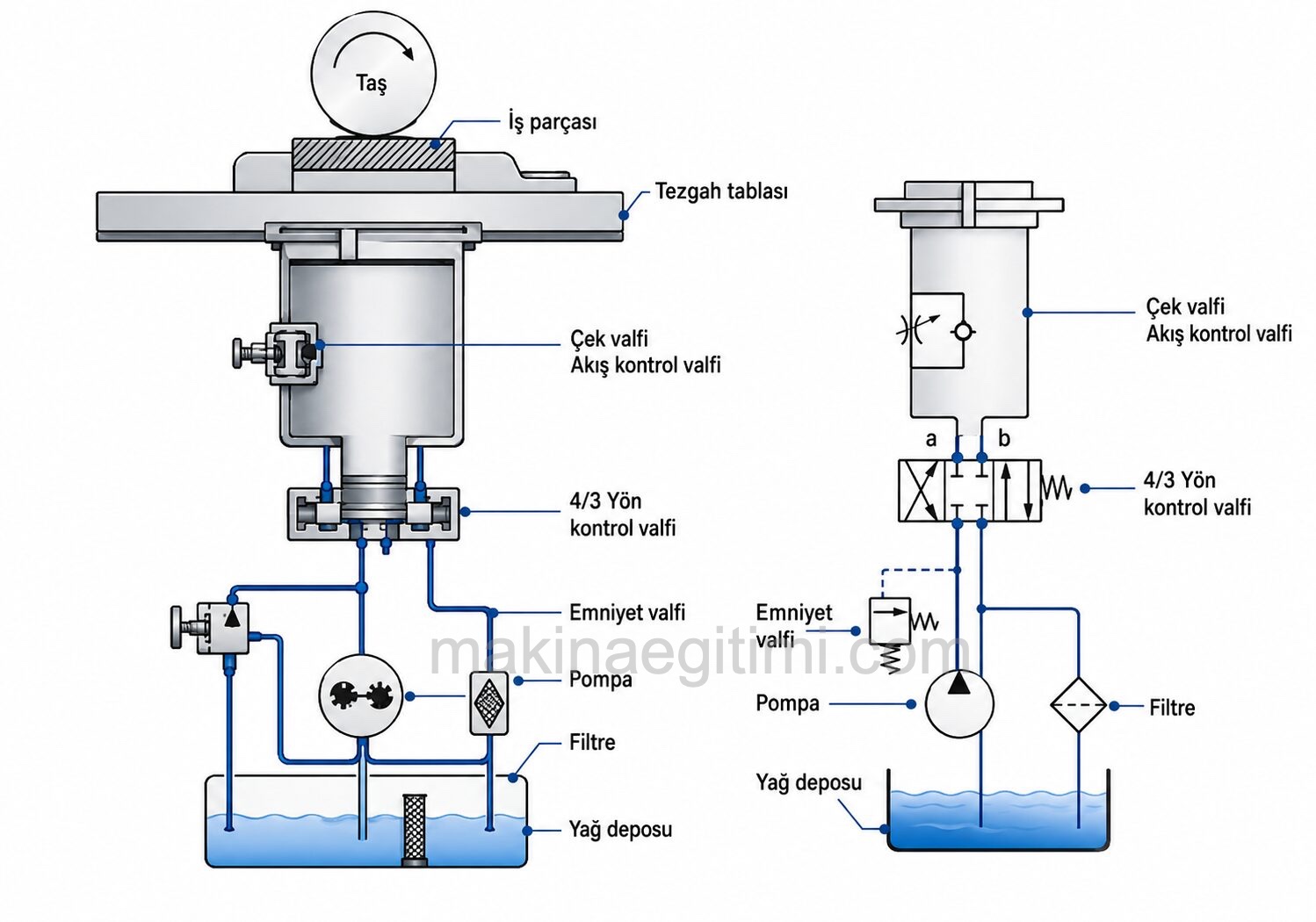
A rough drawing and schematic representation of a grinding machine’s hydraulic circuit. A good example of the subject of hydraulic system applications.
The difference between a hydraulic grinding machine and a shaper is that the cylinder that moves the grinding machine’s table is double-rod. Because of this, the table’s speed is the same in both directions on a grinding machine. To control the table’s speed, an adjustable flow control valve is fitted in the fluid’s path. The cylinder that moves a hydraulic grinding machine’s table is a cushioned cylinder.
Hydraulic Milling Machine
On milling machines, the table the workpiece is clamped to moves in three dimensions: left-right, forward-backward, and up-down. The table’s motion in these three directions can be achieved with mechanical systems as well as hydraulic systems. On copy (tracer) milling machines, the table’s motion in every direction is achieved by means of hydraulic cylinders. In fact, clamping work to a milling machine and the milling cutter’s forward-backward, left-right, and up-down motion are also done with hydraulic systems.
Operating System of a Hydraulic Milling Machine
The image below shows a cross-section image and the circuit’s symbolic diagram for a universal milling machine’s table’s left-right motion.

Fluid coming from the hydraulic pump passes through the directional control valve and enters the cylinder, pushing the milling machine’s table, and the workpiece clamped to it, forward. Meanwhile, the milling cutter removes chips from the work. When the directional control valve’s position is changed, the table moves backward. An adjustable flow control valve fitted in the fluid’s path can also set the table’s speed to the desired value.
Hydraulic Press Machines
Being able to control speed exactly as desired, having a simple and very easy-to-control system, being able to produce very great forces, and being remotely controllable are what’s allowed hydraulic systems to be used in press machines.
Operating System of a Hydraulic Press
In the press shown above, the press head that the male die is attached to is in the up position, and the part to be pressed or bent has been placed in the die. Oil coming from the directional control valve is returning to the reservoir. When the directional control valve is switched to position 1, the fluid passing through the valve enters cylinders no. 1 (the speed cylinders) and moves their pistons downward.
Meanwhile, oil fills the no. 2 power cylinder from the open reservoir. When the die touches the workpiece, the system’s pressure isn’t enough for the pressing operation, so the cylinders’ motion stops briefly. As the system’s pressure rises during this time, the pressurized fluid from the pump opens the pilot-operated sequence valve (5) and enters power cylinder (2). As cylinder no. 2’s pressure rises, it makes the machine perform the pressing or bending operation.
When the directional control valve is switched to position 2, the pressurized fluid coming from the pump enters the no. 1 speed cylinders and pushes their pistons upward. The hydraulic signal taken from the same line opens the no. 4 pilot-operated check valve, letting the oil in cylinder no. 2 return to the open reservoir. This raises the press’s male die back up, ready for the next cycle.

Related Posts
 Flow Control (Speed Control) Valves
  What Are the Differences Between Hydraulic and Pneumatic Systems?
  What Is a Hydraulic Flow Divider? What Does It Do?
  Hydraulic Accumulator Applications
  Spool Overlap in Seat Valves and Spool Valves
  Parts of a Hydraulic Circuit, Illustrated
  Basic Components of Pneumatic Systems
  Elements of a Hydraulic Cylinder