
In this article, we will cover the types of cutting tool wear and their causes, minimizing cutting tool damage, and cutting tool damage.
Types of Cutting Tool Wear
The causes of cutting tool wear can be traced to many different factors. Before examining the factors that affect wear, it is necessary to look at the types of wear that occur on cutting tools, because each type of wear can point to different causes of wear.
Flank Wear
Wear that occurs on the surface of the tool that is in contact with the workpiece is called flank wear.
The friction of this wear zone against the machined surface causes damage to the surface of the material being cut. Flank wear generally takes a non-standard form and occurs in the region close to the edge. The development of flank wear over time is shown in the figure.
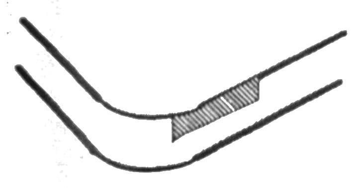

It is not possible to completely eliminate flank wear, but it is possible to take measures to reduce it. Measures that can be taken to reduce flank wear are given in the table below.
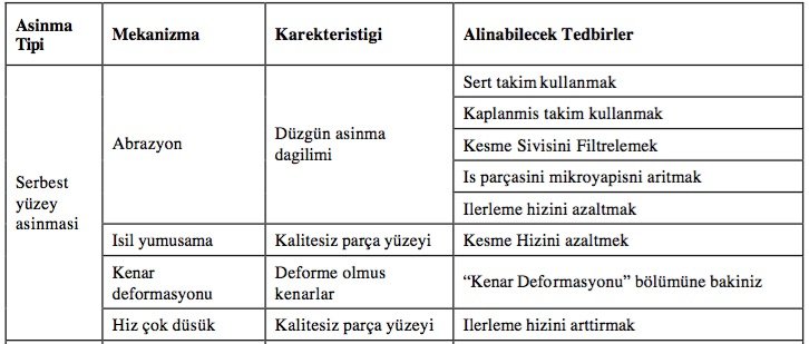
Characteristics of cutting tool flank wear and measures that can be taken
Crater Wear
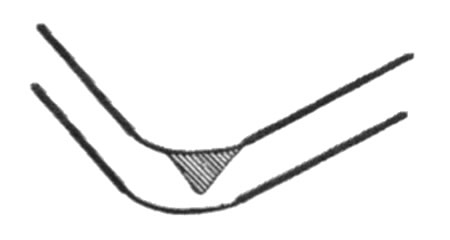
Crater-shaped wear forming on the rake face of the cutting tool. The tool’s rake face is the surface over which the chip removed from the workpiece slides.
Results: A moderate degree of crater wear generally does not limit tool life. Crater formation increases the effective rake angle of the tool and reduces cutting forces.

From this perspective, no drawback is apparent; however, excessive crater wear weakens the cutting edges and this leads to deformation or fracture of the tool. For this reason, excessive crater wear should be avoided, as it shortens tool life and makes reconditioning the tool more difficult.
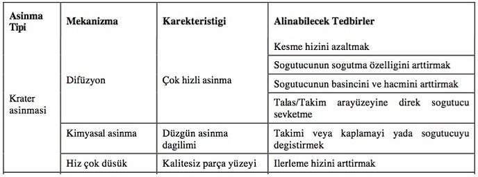
Mitigating measures: Crater wear can be minimized by increasing the chemical stability of the tool material or by reducing the tool’s solubility in the chip.
Notch Wear
In tools used for turning rough surfaces, notch wear occurs at the point of contact between the tool and the unmachined surface or the edge of the chip.
Cause of cutting tool wear: Notch wear can also be caused by an oxidation reaction resulting from a coolant being used, or by corrosion.

Consequences of cutting tool wear: Excessive notch wear makes reconditioning the tool difficult and, especially in ceramic tools, leads to fracture.
Measures to reduce cutting tool wear: Notch wear can be minimized by increasing the entering angle, which increases the contact area between the tool and the workpiece surface, by adjusting the depth of cut in multi-pass machining, and by increasing the thermal hardness and deformation resistance of the tool material.
Nose Wear
This wear occurs on the trace edge near the end of the tool’s flank surface. This wear resembles a combination of flank wear and notch wear.
Causes of cutting tool nose wear: primarily abrasion combined with corrosion or oxidation.
Results: Excessive nose wear reduces the quality of the machined surface.

Thermal and Mechanical Cracks
These cracks occur due to the tool being subjected to variable loads during interrupted cutting, or due to high tool-chip temperatures during machining.
Two types of cracks occur: cracks that form perpendicular to the cutting edges due to variable thermal loads, particularly when coolant is used, and cracks that form parallel to the cutting edges due to variable mechanical loads.
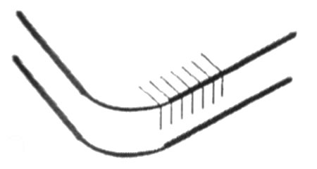

The formation of cracks causes the tool to fail rapidly.

Built-Up Edge (BUE) Formation
BUE (Built-up edge) — causes of cutting tool wear: generally occurs when soft materials (for example, aluminum) are machined at low cutting speeds.
Built-up edge is a particularly significant problem in drilling. It is undesirable because it changes the effective depth of cut (or hole diameter), which makes the depth of cut unstable and consequently results in a poor-quality surface.

Minimization: This can be minimized by using tools with a positive rake angle, using tools with very low surface roughness, using coolants with increased lubricity, directing high-pressure coolant directly onto the rake face, and using higher cutting speeds.

Plastic Deformation
When the cutting pressures across the contact area between the tool and the chip cannot be supported by the tool, plastic deformation occurs on the cutting edges.
Deformation of the cutting edges generally occurs at high feed rates, where cutting-edge forces are high, or at high cutting speeds, where tool hardness decreases along with the increasing cutting speed and heat.
Excessive deformation of the cutting edge leads to reduced dimensional accuracy, poor surface quality, and either excessive flank wear or tool fracture.

Edge Chipping
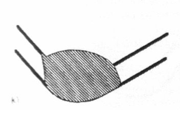
Edge chipping occurs in machining performed with brittle tools such as ceramics, or when machining materials such as metal matrix composites that contain hard or abrasive particles.
Vibration caused by excessive cutting forces or low system rigidity also leads to edge chipping.
Edge chipping reduces the quality of the machined surface, increases flank wear, and can ultimately cause the tool to fracture.
This can be controlled by changing the tool edges or by using tools with increased fracture toughness.
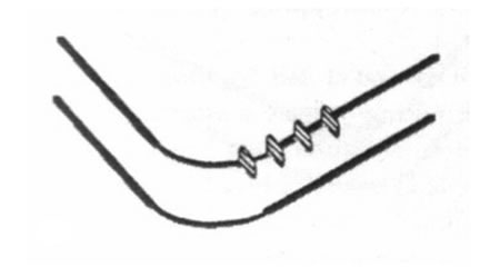

Chip Hammering
This occurs when tough or abrasive-chip-forming materials (for example, stainless steel) are machined with ceramic tools.
Chip hammering occurs when the chip curls back and strikes the tool surface away from the cutting edge. This can be prevented by changing the entering angle, depth of cut, feed rate, or tool nose radius to alter the direction of chip flow.

Tool Fracture
What should be done to prevent tool fracture?
Reducing cutting forces, using strong and more rigid tool holding setups, and using tools with increased fracture toughness will help prevent the cutting tool from fracturing.
Identifying Wear Type
Correctly identifying cutting tool wear helps optimize cutting parameters.
Crater Wear
Crater wear is a pitting that forms on the tool surface due to high temperature and is generally associated with high cutting speed.
Flank Wear
Flank wear results from friction between the tool and the material, and directly affects surface quality.
Related Questions
This wear results from the inevitable friction between the tool and the workpiece, and is a natural consequence of the cutting process. This wear can be slowed by adjusting factors such as cutting speed or tool material, but it cannot be completely eliminated as long as friction exists.
Each type of wear (such as flank wear or crater wear) stems from a different cause; one may be from friction, another from heat. Correctly diagnosing the wear type ensures the correct solution (such as a speed change or a different tool material) is applied.
Related Posts
 Helical Gear Geometry and Strength Calculation
  Causes of Cutting Tool Wear in Milling
  The Software Mechanical Engineers Use the Most
  The Relationship Between Cutting Tools and Surface Roughness
  Chip Types and Forms in Machining
  Chip Control and Chip Breakers in Metal Machining
  Forces Acting on the Crankshaft. Crankshaft Material
  Forces Acting on the Piston and Piston Material