

Formation of Chips
As the tool advances toward the workpiece during machining, the metal ahead of it is compressed. When the compression exceeds the material’s limit, the metal separates from the workpiece and flows plastically in the form of a chip (shear deformation).

Due to primary cutting, the metal flow occurs along the shear plane. The shear plane extends upward at an angle from the uncut surface ahead of the tool. The value of the shear angle depends on the type of material and the cutting conditions (tool angle, cutting speed, etc.). When the shear angle is small, the shear path is long, the chips are thick, and the cutting force is high, and vice versa.
As the chip slides along the face of the tool tip, secondary cutting occurs due to friction. This friction raises the temperature of the machining process, causing the chips to overheat.
Continuous Chip
A continuous chip usually forms as a long ribbon when ductile materials are machined at high cutting speeds.
Discontinuous (Segmented) Chip
A discontinuous chip forms as small segments when machining brittle materials such as cast iron.
Built-up Edge Chip
A built-up edge, which forms at low cutting speeds, can stick to the tool tip and negatively affect surface quality.
Types of Chips
The types of chips formed during the machining of metals are;
- Segmented chip
- Continuous chip
- Built-up edge continuous chips
Segmented (Discontinuous) Chips
Segmented chips generally occur when machining brittle metals such as brass, bronze, or cast iron.
In general, segmented chips are the result of the following machining conditions;
Low feed rate;
High cutting speed;
High tool-chip friction;
Significant depth of cut
Low rake angle.
- Low feed rate;
- Low rake angle;
- High cutting speed;
- High tool-chip friction;
- Significant depth of cut.
Segmented chips provide a clean surface finish, easy chip disposal, longer tool life, and reduced power consumption in brittle metals. In the case of ductile metals, segmented chips generally cause poor surface quality and shorter tool life.
Continuous Chips

Continuous chips generally form when machining malleable metals such as steel, copper, or aluminum at high cutting speeds. During machining, the temperature between the tool tip and the ductile workpiece rises. Each layer of removed metal welds onto the previous layer, forming a long, continuous chip flow.
Continuous chips form under the following machining conditions;
Small depth of cut,
Large rake angle;
High cutting speed;
Low tool-chip friction (use of lubricants or coolants);
Sharp cutting edge.
Continuous chips provide a clean surface finish, longer tool life, and reduced power consumption. On the other hand, disposing of this type of chip is difficult. Chip breakers must be used to improve disposal conditions.
Built-Up Edge (BUE) Continuous Chips
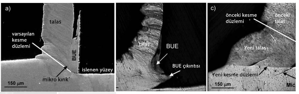
Continuous chip formation with BUE (Built up Edge) results from high friction between the tool and the chip when machining ductile metals. Under these conditions, some chip particles tend to adhere to the cutting tool. The adhered material continues to build up, forming a new cutting edge, until it separates from the tool. During separation, the built-up material adheres to both the chip and the workpiece surface, causing poor surface quality. Another name for BUE formation is “chip welding“.
Continuous chips with a built-up edge occur under the following conditions:
Low rake angle;
Low cutting speed;
High friction forces;
High feed.
Since continuous chips with BUE adversely affect tool life, increase power consumption, and cause poor surface quality, preventing them is very important. Measures such as reducing friction through the use of lubricants, preventing metal-to-metal contact through tool coatings, and lowering the temperature using cutting fluids have a positive effect on preventing chip welding.
Related Questions
This difference comes from the structure of the material being machined. Ductile materials produce a long, continuous ribbon of chip when cut at high speed, while brittle materials such as cast iron break into small segments during cutting.
At a small shear angle, the path followed by the chip lengthens and the chip becomes thicker. Since cutting a thicker chip creates more resistance, the cutting force exerted by the tool also increases.
Related Posts
 Forces Acting on the Piston and Piston Material
  Forces Acting on the Crankshaft. Crankshaft Material Cutting Tool Wear Types and Causes of Wear
  Chip Control and Chip Breakers in Metal Machining
  The Relationship Between Cutting Tools and Surface Roughness
  Helical Gear Geometry and Strength Calculation
  The Software Mechanical Engineers Use the Most
  Causes of Cutting Tool Wear in Milling