
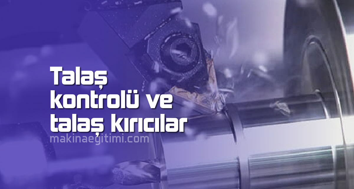
Chip Control
Machining malleable metals like steel at high cutting speeds and large rake angles causes long, stringy chips to form. These sharp-edged, hot, continuous chips coming off at high speed can endanger machine operators’ safety, damage the product by tangling around the tool, and complicate their disposal. Breaking chips down into a manageable geometry is essential.
Improper chip breaking can cause poor surface quality, CNC machine downtime for periodically removing chips, and higher temperatures at the cutting edge. Continuous chips are therefore undesirable.
Chips can break either on their own or through external force. When machining ductile materials, chips tend to curl due to differences in temperature and flow rate. Curled chips can self-break in three different ways:
- Natural fracture due to strain from cooling;
- By striking the workpiece;
- By striking the cutting tool.
The most common method for forced breaking is using a chip breaker.
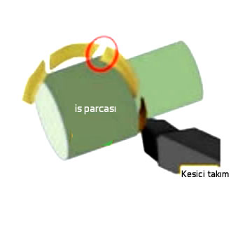
Self-breaking

Breaking by striking the cutting tool

Breaking by striking the workpiece
How do chips actually break? Groove-type chip breakers near the cutting edge cause chips to curl and eject quickly. If chips can be broken to a suitable length by the chip breaker, they won’t wrap around the workpiece, vibration is reduced, and tools aren’t easily damaged. Chip breakers also affect cutting resistance. Reduced cutting resistance can prevent cracking and chipping of the cutting edge caused by vibration. Additionally, lower cutting resistance can reduce load and heat, delaying the progression of tool wear.
There are several factors to consider when selecting a chip breaker. For example, the workpiece material, such as steel, stainless steel, or superalloys. Cutting conditions also play an important role as another factor to consider — cutting speed (Vc – m/min), feed (f: mm/rev), and depth of cut (ap: mm).
Purpose of Chip Breaking
Chip breakers improve operator safety and machining efficiency by breaking long, continuous chips into short pieces.
Geometric Design
Chip breakers use special groove geometries on the cutting insert to make the chip curl and break.
Importance in Automation
Effective chip control is critical, especially on automated CNC machines, to prevent chips from tangling in the machine.
Chip Breakers
Chip evacuation is a critical issue in metal cutting, especially the continuous chips that form when machining ductile materials. Improper evacuation of this type of chip can scratch the workpiece’s machined surface, worsening the resulting surface quality. This scenario can be prevented by using a properly designed chip breaker.
In the world of cutting tools, the chip breaker is a very important component that can determine the workpiece’s quality. However, most people rarely know just how important a chip breaker is.
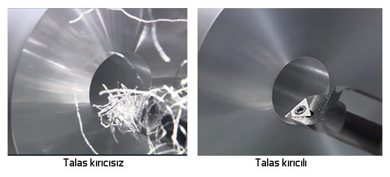
The chip breaker’s most basic function is to force the chip to curl more tightly than it would naturally. This forced curling causes the chip to break by striking the workpiece or the tool. Chip breakers improve machining efficiency by enhancing chip control and reducing cutting forces.

Inserts have different cutting edge and chip breaker geometries for different workpiece materials and depths of cut.
Most modern chip breakers take the form of grooves or obstructions on the cutting tool. Chip breaker design revolves around finding the best geometry to create stress in the chip for a given machining scenario and cause it to break easily.
Groove-type chip breakers contain a small groove behind the leading cutting edge. The groove’s geometry determines the radius of chip curvature.
An obstruction-type chip breaker has a distinct, step-like geometry. The obstruction can be integrated into or attached to the cutting tool. In the case of an “attached” type, it’s possible to adjust them for various machining conditions.
Using Coolant
The last way to aid chip breaking is to use cutting fluid, especially high-pressure coolant (HPC).
During turning, a coolant jet forms a “hydraulic wedge” between the chip and the cutting edge. This not only cools the area better, but also rapidly clears the chip from the cutting edge surface and breaks the chip into smaller pieces.
Scientific Papers on Chip Breakers
- The Influence of Chip Breaker Geometry on Tool Stresses in Turning
- Tailored Chip Breaker Development for Polycrystalline Diamond Inserts: FEM-Based Design and Validation
Related Questions
These chips come off hot, sharp-edged, and at high speed; they can strike the operator or tangle around the tool and workpiece, causing damage. This risk makes breaking chips into controlled, small pieces essential.
The grooved structure positioned near the cutting edge forces the emerging chip to curl in a specific direction. This curling causes the chip to break into small pieces, either through its own strain or by striking the workpiece/tool.
Related Posts
 Forces Acting on the Piston and Piston Material
  The Software Mechanical Engineers Use the Most
  Helical Gear Geometry and Strength Calculation
  Chip Types and Forms in Machining Cutting Tool Wear Types and Causes of Wear
  Forces Acting on the Crankshaft. Crankshaft Material
  Causes of Cutting Tool Wear in Milling
  The Relationship Between Cutting Tools and Surface Roughness