

Variable tensile stress causes the bent part to spring back to some degree. The greatest tensile stress occurs on the outer surface of the bent part, and decreases as it approaches the neutral axis. Both tensile and compressive stresses are zero on the neutral axis.

The figure above shows that tensile and compressive stresses are zero (0) on the neutral axis. In a good bending design, point (x) should be below the maximum tensile stress.
Factors Affecting the Amount of Springback in Bending Dies
- In sheet materials with higher hardness, the elastic metal band is larger and this increases the amount of springback.
- In bends with a small radius of curvature, the amount of springback decreases and cracking occurs in the bend zone.
- In bends with a larger bend angle, the elastic springback region increases and the amount of springback per degree of bend decreases.
- In sheet materials with greater thickness, as the amount of elastic deformation increases, the amount of springback decreases.

The elastic band around the neutral axis of the part being bent is shown in the figure above. The elastic band around the neutral axis produces the springback force, and this force causes the bent part to spring back.
When the force applied to the bent part is removed, due to the springback force the bend angle decreases by the amount of springback, and the bend radius increases. The amount of springback generally depends on the ratio of the bend angle to the die angle, and on whether the sheet material has undergone a normalizing anneal.
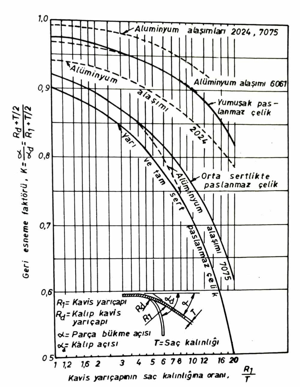
The figure above shows, for aluminum alloys and stainless steel materials, the relationship between the ratio of the bend radius to the sheet material thickness (R1 / T) and the springback factor (K).
The springback amount factor “K” is found using the following formula.

K = Springback factor
R1 = Bend radius of the part (mm)
Rd = Die radius, mm
α = Bend angle of the part, (°)
αd = Die angle, (°)
T = Sheet material thickness, mm

The amount of springback for 90° bends in 2024 and 7075 aluminum materials is given in the table above.

The springback factor (K) for aluminum material at bends other than 90° (above)
For bends other than 90°, the amount of springback is found by multiplying by the coefficient given in the table above, according to the bend angle.
Example Problem for Finding the Amount of Springback
A part to be bent from 1 mm thick 2024 aluminum sheet material has a bend radius of R1 = 3 mm. Find the amount of springback for an 80° bend.
Solution
From the table, the amount of springback for a 90° bend is found to be 3°. Again from the tables above, the coefficient opposite an 80° bend is taken as K = 0.8.
Amount of springback for an 80° bend = 3° x 0.8
= 2° 24′ (2 degrees 24 minutes)
Eliminating the Amount of Springback
Several different methods are used to eliminate springback.
- Increasing the bend angle
- Bottom (coining) bending
- Stretch (draw) bending.
Increasing the Bend Angle to Eliminate Springback
To achieve a bend at the desired angle, the bend angle is increased by the amount of springback. In this type of bending operation, cam-actuated, single-acting dies with a die gap smaller than the sheet material thickness are used.

Figures a, b, c, d above show bending operations performed with extra bend equal to the amount of springback.
Bottom (Coining) Bending to Eliminate Springback
The bend zone is coined between the punch and die so that it cannot deform back. However, this type of bending operation requires a high-tonnage press. Also, the stroke length of the press’s moving (ram) head must be well adjusted. Bending performed this way is called bottom bending. Figure e above.
Stretch (Draw) Bending to Eliminate Springback
In this type of bending operation, the entire material is stretched until it nearly reaches the yield point, and the part, while under tension, is pressed onto the punch. In bending performed this way, the part springs back only slightly; stretch bending is applied to parts with a large radius of curvature. Figure f above shows the stretch bending operation.
Related Posts
 Theory of Deformation in Bent Parts in Bending Dies
  Standard Components Used in Jigs and Fixtures
  Bending Force Calculation for Bending Dies
  Parts of Eccentric Presses
  Stops and Side Gauges in Blanking Dies
  Spinning Mandrels and Spinning Machines
  Blank Diameter Calculation in Drawing Dies
  Die Plates and Their Dimensions