

In this article you can review the pins used for centering in die design, their dimensions, and how they are used in assembly.
Standard Centering Pins

As seen above, standard centering pins are tapered at one end between 5° and 12°. However, for ease of drawing they are shown as in the image below.

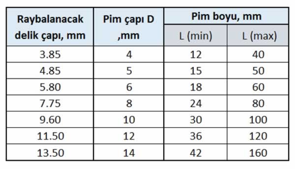
The centering pin dimensions used in small and medium-tonnage dies according to TS 69/15 are given in the table above.
Use of Centering Pins in Assembly
Use in Assembling Two Plates
For Through Holes:

The assembly of two plates drilled all the way through using centering pins is shown in the figure above.

The dimensions of centering pins used for assembling plates thinner than 50 mm are selected from the table above. However, the pin length L(min) cannot be less than 3.D.
For Blind, Side-Blind, and Relieved-Tip Holes
If one of the plates to be assembled is too thick or has a closed body behind it, a blind hole is drilled and a threaded pull-out type centering pin is used (figure a below).
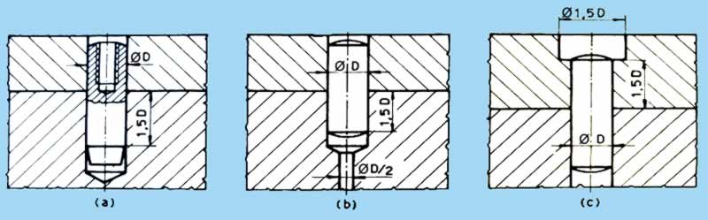
If the back of the plate to be assembled is open but a through pin hole is not desired, a side-blind hole is drilled into the plate or body. To make removing the pin easier, an extension of the pin hole is drilled at a diameter of D/2 (figure b above).
When the plates to be assembled are thicker than 50 mm, the tip of the centering pin hole is relieved to a diameter of 1.5D, avoiding the use of overly long pins (figure c above). In this type of assembly operation, the relieved end of the pin hole is closed with a soft material, for example hard rubber.
Use of Centering Pins in Assembling Three or More Plates
Single or stepped pins are used to position and assemble a large number of plates with centering pins. Because of the large friction surface during assembly with a single pin, the pin may deform or become damaged.
In such cases, material consumption and labor increase. When a stepped pin is used, if one of the pins becomes damaged, making a new one is easy and material consumption is low.
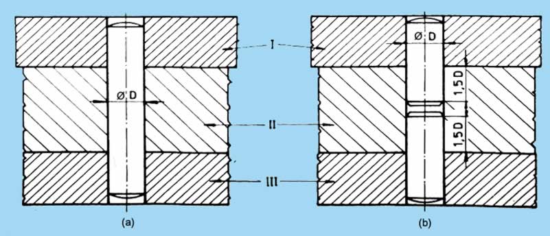
If the thickness of the plates to be assembled is too great, for example exceeding standard pin length, a stepped pin is preferred for the assembly. The figure above shows the use of single and stepped pins when assembling a large number of plates.
Assembly of Hardened Plates
When assembling hardened plates, previously drilled and reamed holes change dimension after heat treatment. In these and similar operations, the pin holes of heat-treated plates are ground whenever possible (figure a below).

If the centering pin hole diameter is too small to be ground, the pin hole in the plates to be assembled is drilled, before heat treatment, at twice the size of the actual pin diameter, and a centering pin with a protective bushing is used for assembling these plates (figure b above).
If one of the plates to be assembled will undergo heat treatment, that plate’s pin hole is drilled larger than the actual pin hole diameter before heat treatment. Thus, a centering pin with a half protective bushing is used to assemble two plates, one hardened and the other soft (not hardened).
Related Posts
 Impact Extrusion Dies
 Parts of Eccentric Presses
 Bending Force Calculation for Bending Dies
 Preventing Wrinkling and Determining Draw Stages in Drawing Dies
 Plastic Injection Molds: Injection System
 Theory of Deformation in Bent Parts in Bending Dies
 Drawer Rail Piercing Die Assembly and Detail Drawings
 Drawing Die Calculation Table