Close Menu
  • MAKİNELER ve İMALAT
    • Tools & Equipment
    • Computer-Aided Drawing
    • CAD/CAM Education
    • CNC Machine Programming
    • Casting Technologies
    • Electrical & Electronics Technologies
    • Hydraulics & Pneumatics
    • Manufacturing Processes
    • Manufacturing Technologies
    • Occupational Safety
    • Mold & Die Design
    • Solid Modeling
    • Welding Technology
    • Machine Elements
    • Mechanical Trade Drawing
    • Materials Science
    • Automotive & Vehicle Technologies
    • Robotics Technologies
    • Health Technologies
    • Defense & Aerospace Technologies
    • Descriptive Geometry
    • Technical Drawing
    • Software & Hardware Technologies
    • Innovative Manufacturing Methods
  • TEKNOLOJİ ve YAŞAM
    • OTOMOBİLLER ve TAŞIT
      • Vehicle & Engine Knowledge
      • Safe Driving
      • Sürüş Destek Sistemleri
    • Genel Kültür
      • Movies & TV Shows
      • Görsel ve Grafik Sanat
      • Books & Literature
      • Music
      • Sports
      • History
      • History of Technology
    • GÜNDELİK YAŞAM TEKNOLOJİLERİ
    • Hobbies & Entertainment
    • Internet Technologies
    • Health
    • Mobile Technologies
Makine Eğitimi
  • Machines & Manufacturing
    Machine Elements
    Hydraulics & Pneumatics
    Technical Drawing
    Computer-Aided Design & Manufacturing
    Basic Manufacturing Processes
    Manufacturing Processes
    Industry Technologies
    Other Technical Courses
    Motion & Power Transmission
    Simple Machines
    Chains & Sprockets
    Shafts & Journals
    Gears
    Cams
    Couplings
    Belts & Pulleys
    Springs
    Bearings
    Keys
    Fastening Joining
    Retaining Rings
    Screws, Bolts & Nuts
    Cotter Pins
    Flanges
    Welding
    Rivets
    Pins & Bolts
    Washers
    Calculators
    Gear Ratio Calculator
    Spring Constant Calculator
    Belt Pulley Ratio Calculator
    Other Machine Elements
    Slides & Linear Guides
    Brakes
    Flywheels
    Clamps
    Shock Absorbers
    Gaskets & O-Rings
    Seals & Sealing Elements
    Hydraulics
    Introduction to Hydraulics & Principles
    Hydraulic Systems & Applications
    Accumulators
    Filters
    Motors
    Pumps
    Valves
    Pneumatics
    Introduction to Pneumatics & Principles
    Pneumatic Systems & Applications
    Pneumatic Circuit Components
    Valves
    Cylinders
    Silencers
    Motors
    Compressors
    Dryers
    Conditioning Units
    Common Topics & Maintenance
    Hydraulic & Pneumatic Maintenance
    Study Notes, Exams & Tests
    Technical Drawing
    Introduction to Technical Drawing
    Geometric Drawings
    Perspective & Projection
    Orthographic Views
    Dimensioning
    Sectioning
    Assembly & Detail Drawings
    Tolerances
    Surface Finish Symbols
    Mechanical Engineering Drawing
    Screws, Bolts & Nuts
    Pulley Drawings
    Gear Drawings
    Shafts & Journals
    Bearing Drawings
    Pins & Bolts
    Spring Drawings
    Welds in Technical Drawing
    Washers
    Cotter Pins
    Technical Drawing Exercises
    Mechanical Drawing Exercises
    Gear Exercises
    View Extraction Exercises
    Pulley Exercises
    Pin & Bolt Exercises
    Threaded Fastening Exercises
    Descriptive Geometry
    Computer-Aided Drawing
    AutoCAD Drawing Lessons
    Solid Modeling & Animation
    Solid Model Drawing Files
    Solid Model Assembly Examples
    Solid Model Drawing Lessons
    3D CAD Software Reviews
    Solid Modeling Exercises
    CNC Programming
    CAM
    Measurement & Inspection
    Dial Indicators
    Calipers
    Gauges
    Micrometers
    Materials Science
    Steels
    Cast Iron
    Aluminum
    Plastics
    Material Testing & Hardness Measurement
    Occupational Safety
    Workshop Safety
    Safety When Working With Electricity
    Machine Safety Rules
    Hand Operations
    Filing
    Marking
    Cutting Operations
    Reaming
    Tapping
    Threading With a Die
    Drill Bit Sharpening
    Working With Machines
    Basic Turning Operations
    Basic Milling Operations
    Shaper Machine
    Machining
    Turning
    Milling
    Grinding
    Innovative Manufacturing Methods
    EDM (Electrical Discharge Machining)
    Laser Machining
    Waterjet Machining
    3D Printing
    3D Scanners
    Welding
    Rolling
    Casting
    Mold & Die Design
    Mechanical & Hydraulic Presses
    Blanking & Piercing Dies
    Bending Dies
    Drawing Dies
    Plastic Injection Molds
    Extrusion Dies
    Compound Dies
    Progressive Dies
    Blow Molds
    Spinning Dies
    Spray Molds
    Manufacturing of Machine Parts
    Automotive & Vehicle Technologies
    Motor Vehicle Manufacturing
    Raw Material Production
    History of Technology
    Health & Medical Technologies
    Defense & Aerospace
    Robotics Technologies
    Software & Hardware Technologies
    Mechanics - Strength of Materials
    Physics Topics
  • Technology & Life
    Hobbies & Entertainment
    Sports
    Music
    Vehicle & Engine Knowledge
    Vehicle Maintenance & Repair
    Safe Driving
    Driver Assistance Systems
    History
    Movies & TV Shows
    Books & Literature
    Computers & Internet
    Computer Tips
    Software Reviews
    Hardware & Peripherals
    Practical & Safe Internet Use
    Visual & Graphic Art
    Mobile Technologies
    Travel
    Science
    Health
    First Aid Knowledge
    Everyday Technologies
Makine Eğitimi
Home»Manufacturing Technologies»Broaching. What Is It. How Is It Done
29 August 2026Updated:3 September 2026

Broaching. What Is It. How Is It Done

Broaching. What is it. Title image

Broaching

Broaching is the process of removing a layer of material of the desired width and depth, generally in a single pass, using a thin bar-type cutting tool with a series of progressively larger cutting edges. It is also called “tığ çekme” in Turkish.

  • Broaching
    • Internal Broaching
    • External Broaching
    • Advantages of broaching
    • Weaknesses of the broaching process
    • Broaching Tools
      • Broaching tool terminology
    • Where Is the Broaching Technique Used
  • Related Questions

In broaching, the broaching tool is generally a profiled die for the internal or external surfaces of the workpiece. Broaching is used in mass production wherever profiles with high surface quality and great dimensional accuracy need to be produced. Because the broach (cutting) tool is very expensive, it is only economical for large quantities of parts.

Broach tool tooth geometry

The broaching method is divided into two groups: internal broaching and external broaching.

internal and external broaching
Examples of external (left) and internal (right) broaching

Internal Broaching

internal broaching

When internal surfaces are to be broached, the part must already have a starting hole for the broach.

In internal broaching, profiles are broached outward from a hole. The workpiece is not clamped; it is simply slid along the tool’s guide bar and placed flat against the machine’s workpiece support die. The broaching tool is pulled through the hole by its pull-end shank, producing the desired profile.
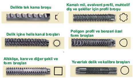
internal broaching tools

In screw broaching (cutting a helical groove), the teeth of the broaching tool are made in a screw shape. The workpiece is mounted so it can rotate, placed inside a holding jaw.
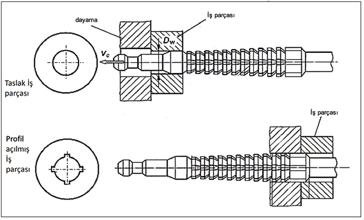
internal profile broaching
Broaching a hole and cutting a 4-sided keyway (above)

During broaching, the workpiece is rotated by the sides of the teeth so as to produce the lead angle of the groove being broached.

internal broach tool
Video of how broaching is performed

External Broaching

In external broaching, the tool is guided along the outside of the workpiece. Because of the large cutting and pull-out forces involved, the tool must be rigidly clamped and supported.

External broaching tools

In circumferential (surround) broaching (tube and shell broaching), the tool completely surrounds the workpiece, making it possible, for example, to broach an external gear tooth form in a single pull. The tool is made in sections.

External broaching operation on a CNC lathe

Advantages of broaching

Provides high surface quality
Completed in a single pass.
Cutting speed is high.
Provides dimensional accuracy.
Allows complex profiles to be produced.
Provides easy and cheap labor.
Machined parts are identical

Weaknesses of the broaching process

where is broaching used

Broach tool cost is high for large and complex-shaped parts.
It is not possible to machine very small parts.
Parts must be firmly clamped.
Not much stock can be removed

Broaching Tools

Broaching tools are generally made of tool steel (such as M2 HSS, PM-M4 HSS, PM-T15 HSS). There are also carbide-tipped versions used on CNC machines.
broaching tools

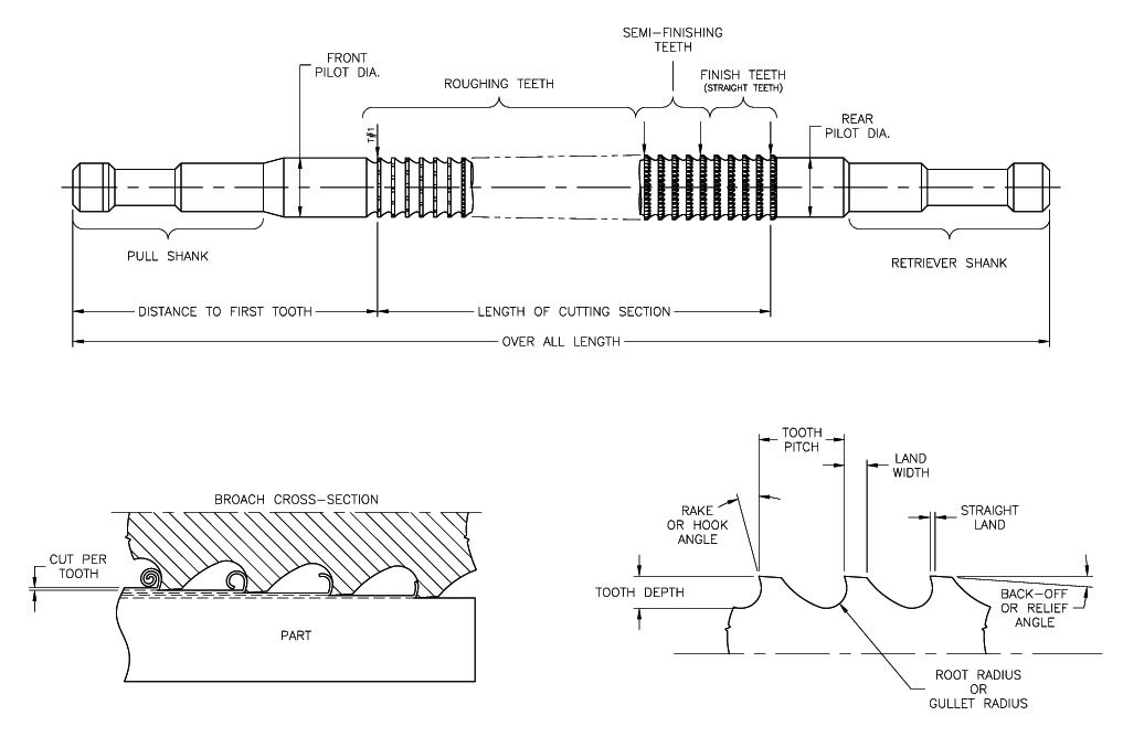
Broaching tools consist of a shank, a guide bar, the tooth section, a rear guide section, and a rear end section. In the cutting portion of the tool, the chip thickness (h) is produced by progressively stepping up the cutting-edge teeth.

how is broaching done
Views from internal and external broaching operations (above)
internal broaching tools
Internal broaching tools

The roughing teeth take on the largest share of material removal (h=0.2 mm), while the finishing section consists of at least 3 teeth (h<0.2 mm). The last finishing tooth and the first burnishing tooth are made to the manufacturing size. The tool has at least 3 finishing (burnishing) teeth of the same profile and dimensions, which burnish (calibrate) the surfaces of the workpiece. These also serve as a reference during resharpening.

External surface (form) broaching tools

The cutting-edge angle and chip clearance are determined based on the length of the surfaces to be broached and the machinability of the workpiece material. A pilot hole is drilled before broaching. The relief angle is very small (1.5°~2°), so that this value stays the same through resharpening of the tooth face. Chip-breaker grooves on the relief surfaces prevent chips from jamming between the side relief surfaces and the broached surfaces and cracking them. The broach used during broaching should be selected so that 2 to 6 teeth are cutting at the same time. The more teeth in contact with the material at once, the smoother the broaching operation proceeds.

A tool for broaching a groove
A video explaining how broaching tools are made

Broaching tool terminology

broaching terminology

Where Is the Broaching Technique Used

Any material that can be machined using cutting techniques can also be machined by broaching. Widely used metal alloys, some plastics, hard rubbers, wood, composite materials, and graphite can all be machined by broaching. Steel materials with a hardness between 18-32 HRC can be machined with this technique. Cast iron, brass, bronze, aluminum, and magnesium can be machined at high cutting speeds.

examples of broached parts

Broaching is used to produce various grooves, keyways, flat or complex-shaped surfaces, rack gears, and internal gears. The broaching technique is used in the automotive, aerospace, and hand-tool manufacturing industries, in parts made by the milling technique, in white-goods manufacturing, in firearms parts production, in lock manufacturing, and in electric motor production. It is also used in the firearms industry to cut rifling in gun barrels.

Broach Tooth Rise


Each tooth on a broaching tool grows progressively, removing a little more material than the tooth before it.

Single-Pass Finishing


Broaching is an efficient method that can machine complex internal profiles to their final dimension, usually in a single pass.

High Investment Cost


Because broach tools are complex and expensive to produce, the method is generally preferred for high-volume mass production.

Related Questions

The tool is a precisely and specially manufactured part with a large number of progressively increasing cutting teeth. Because this manufacturing cost can only be brought down per part by producing a large number of identical parts, it is not economical for small production runs.

The broaching tool is pulled through a pre-drilled hole, and this pulling motion already holds the part firmly against the support die. The operation can also be completed without needing any clamping mechanism.

Related Posts

Plastic Injection Molding Plastic Injection Molding What Is Honing? How Is It Done? Where Is It Used? What Is Honing? How Is It Done? Where Is It Used? Jetta VS5 body being welded by robotic arms on the production line The Complete Manufacturing Process of the China-Made Jetta VS5 Laser Cutting Working Principle Laser Cutting Working Principle, Advantages and Disadvantages Çelik Üretim Yöntemleri Steel Production Methods transfer molding machine Transfer Molding and Transfer Molding Dies Dişli Çark Üretim Yöntemleri Gear Manufacturing Methods Gear Making by the Hobbing Method Gear Making by the Hobbing Method
Manufacturing of Machine Parts
Share. Facebook Twitter WhatsApp Tumblr Email Telegram Copy Link

Leave A Reply Cancel Reply

Steering Wheel Grip and Turning Techniques
How Is a Camshaft Checked?
  • Contact
  • Terms of Service
  • Privacy & Cookie Policy

Type above and press Enter to search. Press Esc to cancel.