
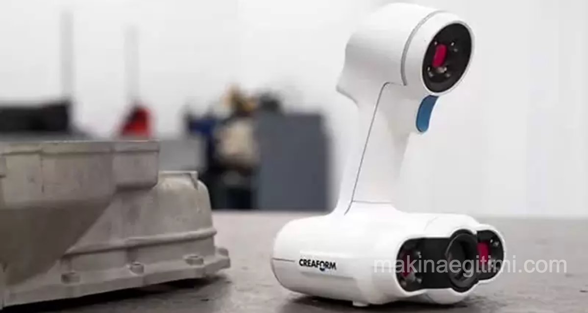
There are 3 most commonly preferred methods for 3D scanning. The choice among these methods can vary depending on your project and resources.
Laser 3D Scanning
Laser 3D scanning is the most widely used 3D scanning technique. Well-known laser 3D scanners measure how long it takes for a laser to hit an object and return.
Because the speed of light is precisely known, the time it takes for the laser to make the full round trip gives the exact distance between the 3D scanner and the object. To measure the distance precisely, the 3D scanner calculates millions of laser pulses with accuracy down to the picosecond (1 picosecond equals 0.000000000001 seconds!).
Since each measurement only collects a single point, the 3D scanner needs to rotate its laser 360 degrees around that point. To do this, a mirror that redirects the laser beam is usually fitted to the 3D scanner.
This laser scanning technique is excellent for measuring and inspecting complex geometries. It allows measurements and data to be taken from locations that would be impractical with traditional methods!
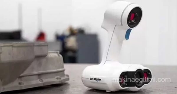
A scanner that uses laser light works a bit like a camera: it can only capture what is within its field of view. In this process, a laser point or line is projected from the device onto an object, and a sensor measures the distance to that object’s surface.
By processing this data, it can be converted into a triangulated mesh and then into a CAD model.
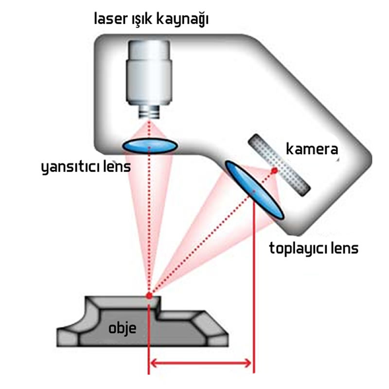
3D scanning with a laser is the fastest, most accurate, and most automated way to obtain 3D digital data for reverse engineering. Again, using specialized software, the point cloud data is used to build a 3D CAD model of the part’s geometry. The CAD model allows the scanned object to be reproduced exactly, or the object can be modified on the CAD model to correct defects. Depending on what results the application needs, laser scanning can provide a surface model or a more complex solid model.
Structured Light Scanning
Structured light scanners also use trigonometric triangulation, but instead of relying on laser light, these systems use a projector to display a series of linear patterns onto an object. They then calculate the distance from the scanner to the object’s surface by examining the edges of each line in the pattern. Essentially, instead of seeing a laser line, the camera sees the edge of the projected pattern and calculates the distance in a similar way.

The projected structured light used for 3D scanning can be white or blue, and can be generated by various types of projectors, such as Digital Light Processing (DLP) technology. The projected pattern is usually a series of light stripes, but it can also be a random dot matrix.
The main advantages of structured light technology for 3D scanning are its speed and resolution, and its non-harmful light can even be used for 3D body scanning.
However, structured light 3D scanners are sensitive to lighting conditions and struggle to work outdoors in broad daylight.
Structured light scanning is used in facial and environmental recognition technologies.
Laser Scanning Precision
Laser 3D scanning can achieve micron-level precision by projecting a laser beam onto the object’s surface.
Photogrammetry Cost
Since photogrammetry requires no special hardware, it is a far cheaper method compared to laser scanning.
Point Cloud Generation
Both methods produce a “point cloud” made up of millions of points representing the surface of the scanned object.
Photogrammetry
The principle of photogrammetry is to analyze several photographs of a static subject taken from different viewpoints and automatically detect the pixels that correspond to a unique physical point.
The main challenge of this 3D scanning technology is examining dozens or hundreds of photographs and thousands of points with high accuracy. Running such photogrammetry algorithms requires a very powerful computer.
The main advantages of photogrammetry as a 3D scanning technology are its capture speed and its ability to capture colors and textures. Photogrammetric technology also has the ability to reconstruct large-scale subjects, such as landscapes or monuments photographed from the ground or from the air, for example with a drone.
The main challenge of this 3D scanning technology is examining dozens or hundreds of photographs and thousands of points with high accuracy. Running such photogrammetry algorithms requires a very powerful computer.
The quality of the results produced by photogrammetry technology depends on the resolution of the input photographs. Depending on your software and computer setup, this technology can be quite slow.

Above, we see the wreck of the Titanic, which sank into the Atlantic waters in 1912. Before sinking, the Titanic broke into two pieces, and the pieces settled on the seabed at a depth of roughly 4,000 meters. Taking a photograph of a shipwreck at that depth, like the one above, is impossible, because the water at that depth is pitch dark. The image you see above was created using the photogrammetry method — that is, by digitally stitching together thousands of close-up photographs of the ship into a 3D model.
Contact-Based 3D Scanning Technology
Contact-based 3D scanning is also known as digitizing. This 3D scanning technology refers to a form of 3D data collection based on physical contact.
Contact 3D scanners examine an object through physical touch while the object is held firmly in place. A touch probe is moved along the surface to record 3D information. For greater precision, the probe is sometimes mounted on an articulated arm that can capture all relevant configurations and angles.
Certain specialized configurations of contact-based 3D scanners are called Coordinate Measuring Machines (CMM).
Contact 3D scanning is widely used to perform quality control after manufacturing or during maintenance operations. The main advantages of contact technology for 3D scanning are its precision and its ability to 3D scan transparent or reflective surfaces.
The disadvantages of contact 3D scanning technology are its slowness and its inability to work with organic, freeform shapes.
Related Questions
Because the speed of light is constant and precisely known, distance is calculated by measuring the round-trip time of the laser to the object and back. Since the device measures this time at the picosecond level, the result is extremely precise.
Each laser shot only measures the distance to a single point. To capture the shape of the object’s entire surface, the laser must be aimed at different angles to collect thousands of points.
Related Posts
 Where Are 3D Scanners Used
  Stages of Manufacturing with 3D Printers
  What Is Wire EDM, How Does It Work?
  Motion Capture Technology
  3D Printer Applications Today and in the Future
  Properties of Laser and Laser Devices Used in Medicine
  What Can a Waterjet Cut? What Can It Not Cut?
  3D Scanning – What Is 3D Scanning?