

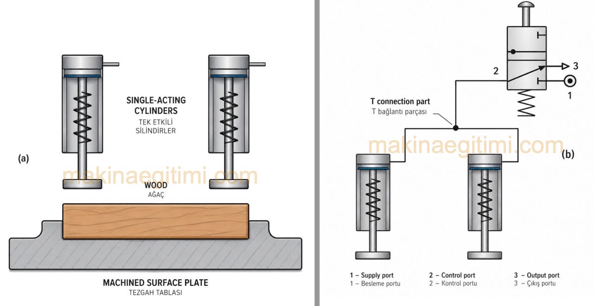
In some pneumatic systems, it may be necessary to control more than one cylinder at the same time through a single valve. For example, to move two vises on a machine table simultaneously, two single-acting cylinders can be operated using a shared valve.
In this type of connection, where two single-acting cylinders are controlled by a 3-way valve, a T-fitting is used to feed the cylinders. For both cylinders to move simultaneously and as consistently as possible, the tubing running from the T-fitting to each cylinder must be the same length. This arrangement is shown in the figure below.
Similarly, connecting three single-acting cylinders to a 3-way valve will require a 4-way fitting. A 4-way fitting can be made by joining two T-fittings with a very short piece of plastic tubing (below).

A 5-way valve can be used to operate two or more double-acting cylinders. This type of circuit requires 2 T-fittings to split the air supply and exhaust lines (below).

When the 5-way valve is in position 1, both double-acting cylinders move in the negative direction. When the 5-way valve is shifted to the second position, the double-acting cylinders switch to positive motion.

Controlling a Double-Acting Cylinder with 1 Pilot Valve
Valves with dual pressure inlets are commonly used, especially for operating double-acting cylinders. For this reason, they are sometimes referred to in the literature as a “control valve.”
In applications where the control valve needs to be operated remotely, the signal sent to the valve can be generated by means of a pilot valve. The pilot valve is itself a 5-way valve and can be used in various configurations. The pilot valve’s main job is to generate the pneumatic control signal that will actuate the control valve. This signal is transmitted to the control valve, which in turn drives the motion of the double-acting cylinder.


Pneumatic circuit with the cylinder in the negative and positive position (above)
Circuit Description
In pilot-valve circuits, the signal control line between the pilot valve and the control valve is shown with a dashed line, while the air lines between the control valve and the cylinder are shown with a solid line.
When the 5-way pilot valve is in the open position, main air enters the pilot valve through port 1 and exits through port 4. This airflow creates a control signal at ports 1-2 of the dual-pressure-inlet 5-way control valve. In this state, the main air keeps the cylinder piston in the negative position.
When the pilot valve is switched to the closed position (as shown in the figure on the right above), the resulting air signal is redirected from the 1-2 connection to the 1-4 signal connection. The air pressure at the 1-4 connection shifts the spool inside the control valve. As the air exits the valve through port 4, the cylinder piston moves in the positive direction.
Controlling a Double-Acting Cylinder with 2 Pilot Valves
A double-acting cylinder can also be controlled using two pilot valves. In this system, the control valve is a dual-pressure-inlet 5-way valve, while the pilot valves are spring-return, push-button-operated 3-way valves.

When the push-button on the inlet-side 3-way pilot valve is pressed, an air signal is sent to ports 1-2 of the control valve. As a result, main air exits through port 2 of the control valve, moving the cylinder piston in the negative direction. Since the pilot valve is spring-return, it returns to its starting position once the button is released, cutting off the signal.

When the push-button on the outlet-side 3-way pilot valve is pressed, the air signal is instead directed to ports 1-4 of the control valve. This signal shifts the control valve’s spool, causing the main airflow to exit through port 4. As a result, the cylinder piston moves in the positive direction.

Related Posts
 What Is a Solenoid Valve, How Does It Work?
  Hydraulic Filtration Systems
  Hydraulic Cylinder Force Calculator
  Hydraulic Oil Selection and Properties Required in Hydraulic Oils
  4-Way 2-Position Directional Control Valves
  What Is a Pneumatic Compressor, What Does It Do?
  Parts of a Hydraulic Circuit, Illustrated
  Hydraulic Applications – Clamping Fixture