Mechanical engineering education – Hydraulics-pneumatics lesson notes, OR valve topics:
OR Valve Explanation
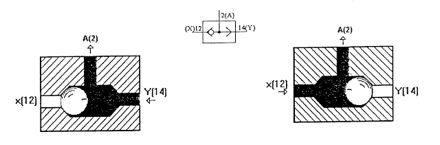

The OR Valve has two control connections, 12 (X) and 14 (Y), and one working connection, 2 (A). When pressurized air arrives from either the X or Y line, the signal passes through to the working line (a signal appears at line 2). At the control connection under pressure, the air from the side with the higher pressure passes through to the working line (the higher pressure connects to the working connection).
The OR Valve implements the logic of an OR function, or is used as the OR element in digital technique.
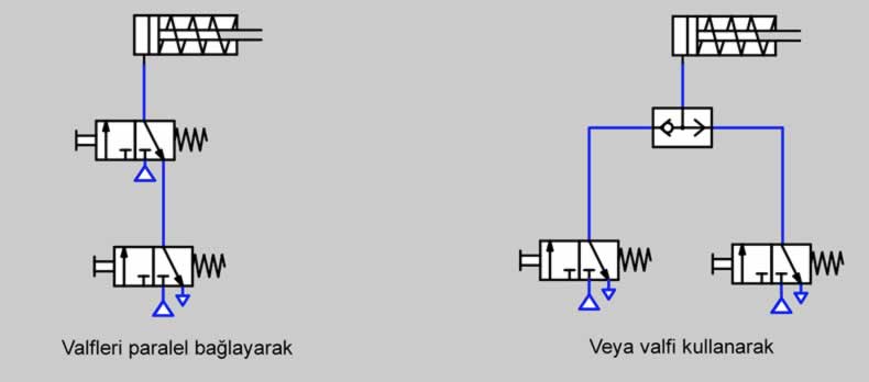
Controlling a single-acting cylinder by wiring it in parallel without an OR valve. (top left) Controlling it using an OR valve (top right)

Controlling a single-acting cylinder by pressing any one of four separate valves (above)
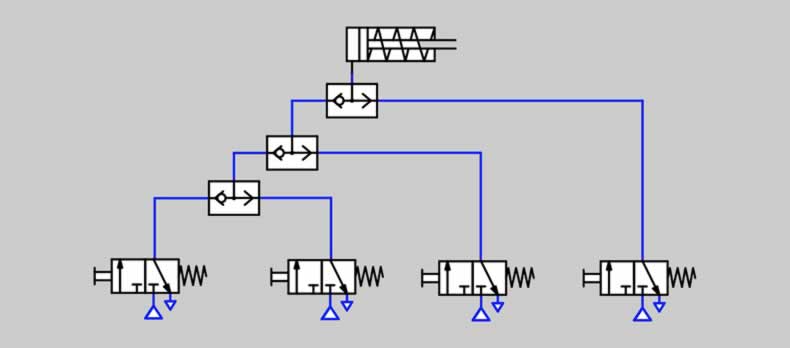
Controlling a single-acting cylinder by pressing any one of 4 separate valves (above)
OR VALVE SAMPLE APPLICATION

-Building and explaining the circuit
APPLICATION:

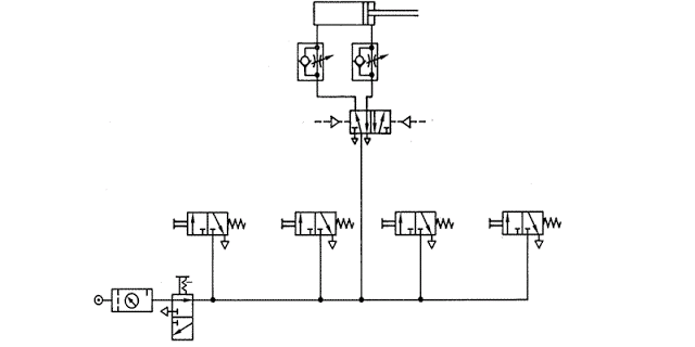
A garage door is to be triggered pneumatically, opened from inside, and both opened and closed from outside. For this, there must be two buttons outside the garage and one button inside. The door’s opening and closing speed should be adjustable;
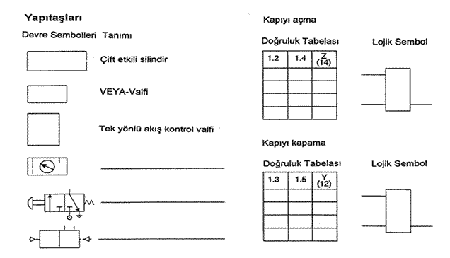
- Prepare the truth table,
- Complete the circuit symbols and build the circuit.
- Why is an OR Valve needed to solve the problem — could an AND valve be used to solve the problem instead?
Related Posts