

In this section, AND valve explanation and applications. What is an AND valve? Where is an AND valve used? How does the operating system of an AND valve work? We will cover topics like these.
What Is an AND Valve?
An AND valve has two control connections (X and Y) and one outlet (A). Pressurized air can only pass through if there is a control signal on both sides. If only one control signal is present, the flow is blocked. If the control signals arrive at different times, the one that arrives last is the one that reaches the outlet.

Where the pressures differ, the higher control pressure closes the valve. The lower one passes through to the outlet. Functionally, the AND valve corresponds to two series-connected 3/2 directional control valves, either triggered or spring-return.
The AND valve carries out the logic of an AND function and is used as the AND element in digital technique.
Where Is an AND Valve Used?
An AND valve can be used wherever two triggers have to be operated at the same time. Take, for example, a scenario in which a worker operating a press has to press two buttons at once to bring the press down — one button on the worker’s right and one on the left. Because both of the worker’s hands are then occupied, there is no danger of a hand being caught as the press comes down.

Two-Hand Control Pneumatic Safety Circuit
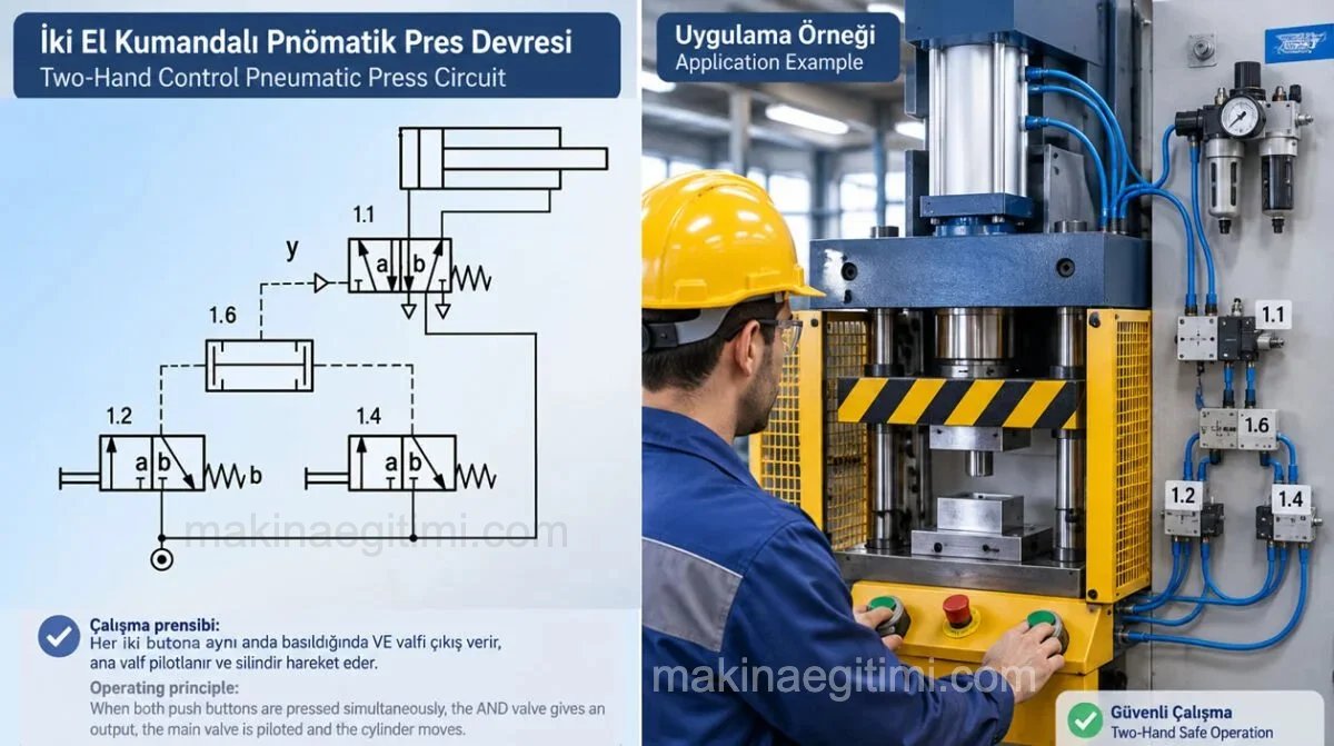
Let us go through the diagram component by component, and then follow it through in working order.
Main directional control valve:
The valve controlling the cylinder at the top. It has a spring on its right-hand side and the Y pilot control on its left.
No Y signal → the valve stays in the spring position
Y signal present → the valve shifts to the other position.
Air is directed through this valve into the two chambers of the cylinder, producing the forward and return movement of the piston.

Left-hand button: A 3/2 spring-return button valve. It produces no signal while the button is not pressed. When it is pressed, compressed air is sent on towards 1.6.
Right-hand button: Identical to 1.2. That is:
1.2 = left-hand control
1.4 = right-hand control
Two-pressure valve / AND logic element: This is the most important part of the circuit.
1.6 has two inlets: this element works on AND logic. In other words, for it to give an output, pressure has to arrive from 1.2 AND 1.4 at the same time. If only one button is pressed, no Y signal is produced.
What does the system do in its normal state?
Let us say that in the initial state both buttons are released.
1.2 → released
1.4 → released
        ↓
      1.6
        ↓
      Y = none
        ↓
      1.1 in spring position
So 1.1 stays in the position into which the spring on its right pushes it. In this position the main valve sends compressed air into the relevant chamber of the cylinder and connects the other chamber to exhaust. The cylinder is thus held in its initial position.
What happens if we press only the left button?
Say we press 1.2. The pressure goes:
Pressure
  ↓
1.2
  ↓
first inlet of 1.6
But 1.4 is still released. 1.6 produces no Y signal. Therefore: 1.1 does not move. Nor does the cylinder.
And if we press only the right button?
The same thing happens.
1.2 = 0
1.4 = 1
0 AND 1 = 0
Again: Y = 0
The main valve 1.1 stays in the spring position. The cylinder does not move.
If we press both buttons at the same time
This is where the real purpose of the circuit comes out. When the operator presses both buttons:
1.2 = 1
1.4 = 1
1.6:
1 AND 1 = 1
So the Y pilot signal appears at the outlet of 1.6.
The flow: the Y signal reaches the pilot control on the left-hand side of 1.1. 1.1 moves against its spring and shifts to the other position. As a result the air connections on the two sides of the cylinder are swapped. The cylinder moves in the other direction.
Why are two buttons used?
The real purpose is operator safety.
Suppose the cylinder at the top is operating a press. If there were only one button:
Operator → presses the button
             ↓
          cylinder
             ↓
           PRESS
The operator’s other hand could still be in the press area. That creates a serious risk of trapping or crushing.
With two-hand control, however:
Left hand  → 1.2 ─┐
                  ├→ AND → Y → 1.1 → Cylinder
Right hand → 1.4 ─┘
Because both of the operator’s hands have to be on the buttons, the aim is to keep the hands away from the danger zone during the cycle.
Truth table:
| Left button | Right button | Y | Cylinder cycle |
|---|---|---|---|
| 0 | 0 | 0 | No motion |
| 1 | 0 | 0 | No motion |
| 0 | 1 | 0 | No motion |
| 1 | 1 | 1 | Moves |
A very important detail: the question of “at the same time”
There is a nuance here. The simple two-pressure valve in the diagram may not be enough on its own for a genuinely safe two-hand control.
For instance, the operator presses the left button first, then the right one.
If pressure is present on both sides at the moment the second button is pressed, 1.6 can give an output.
For that reason, in modern machine safety, rather than using only:
two 3/2 valves plus an AND valve, safety functions such as synchronism, anti-tie-down and restart interlock also have to be taken into account.
For example, it should not be possible to start the cycle by holding one button down and pressing the other one repeatedly.
It is therefore right to think of this diagram as “the basic operating principle of a two-hand control pneumatic circuit”; the full requirements of a real safety circuit should not be inferred from such a simple diagram.
Related Posts
 Pneumatic Valves and Their Types
 Introduction to Pneumatics and Definitions
 What Is a Hydraulic Pump. How Does It Work?
 Types of Pneumatic Motors
 Hydraulic Applications – Pressure Reducing Valve
 Safety Rules for Workers on Hydraulic and Pneumatic Machines
 Design of Open and Closed Hydraulic Circuits
 Basic Components of Pneumatic Systems