Close Menu
  • MAKİNELER ve İMALAT
    • Tools & Equipment
    • Computer-Aided Drawing
    • CAD/CAM Education
    • CNC Machine Programming
    • Casting Technologies
    • Electrical & Electronics Technologies
    • Hydraulics & Pneumatics
    • Manufacturing Processes
    • Manufacturing Technologies
    • Occupational Safety
    • Mold & Die Design
    • Solid Modeling
    • Welding Technology
    • Machine Elements
    • Mechanical Trade Drawing
    • Materials Science
    • Automotive & Vehicle Technologies
    • Robotics Technologies
    • Health Technologies
    • Defense & Aerospace Technologies
    • Descriptive Geometry
    • Technical Drawing
    • Software & Hardware Technologies
    • Innovative Manufacturing Methods
  • TEKNOLOJİ ve YAŞAM
    • OTOMOBİLLER ve TAŞIT
      • Vehicle & Engine Knowledge
      • Safe Driving
      • Sürüş Destek Sistemleri
    • Genel Kültür
      • Movies & TV Shows
      • Görsel ve Grafik Sanat
      • Books & Literature
      • Music
      • Sports
      • History
      • History of Technology
    • GÜNDELİK YAŞAM TEKNOLOJİLERİ
    • Hobbies & Entertainment
    • Internet Technologies
    • Health
    • Mobile Technologies
Makine Eğitimi
  • Machines & Manufacturing
    Machine Elements
    Hydraulics & Pneumatics
    Technical Drawing
    Computer-Aided Design & Manufacturing
    Basic Manufacturing Processes
    Manufacturing Processes
    Industry Technologies
    Other Technical Courses
    Motion & Power Transmission
    Simple Machines
    Chains & Sprockets
    Shafts & Journals
    Gears
    Cams
    Couplings
    Belts & Pulleys
    Springs
    Bearings
    Keys
    Fastening Joining
    Retaining Rings
    Screws, Bolts & Nuts
    Cotter Pins
    Flanges
    Welding
    Rivets
    Pins & Bolts
    Washers
    Calculators
    Gear Ratio Calculator
    Spring Constant Calculator
    Belt Pulley Ratio Calculator
    Other Machine Elements
    Slides & Linear Guides
    Brakes
    Flywheels
    Clamps
    Shock Absorbers
    Gaskets & O-Rings
    Seals & Sealing Elements
    Hydraulics
    Introduction to Hydraulics & Principles
    Hydraulic Systems & Applications
    Accumulators
    Filters
    Motors
    Pumps
    Valves
    Pneumatics
    Introduction to Pneumatics & Principles
    Pneumatic Systems & Applications
    Pneumatic Circuit Components
    Valves
    Cylinders
    Silencers
    Motors
    Compressors
    Dryers
    Conditioning Units
    Common Topics & Maintenance
    Hydraulic & Pneumatic Maintenance
    Study Notes, Exams & Tests
    Technical Drawing
    Introduction to Technical Drawing
    Geometric Drawings
    Perspective & Projection
    Orthographic Views
    Dimensioning
    Sectioning
    Assembly & Detail Drawings
    Tolerances
    Surface Finish Symbols
    Mechanical Engineering Drawing
    Screws, Bolts & Nuts
    Pulley Drawings
    Gear Drawings
    Shafts & Journals
    Bearing Drawings
    Pins & Bolts
    Spring Drawings
    Welds in Technical Drawing
    Washers
    Cotter Pins
    Technical Drawing Exercises
    Mechanical Drawing Exercises
    Gear Exercises
    View Extraction Exercises
    Pulley Exercises
    Pin & Bolt Exercises
    Threaded Fastening Exercises
    Descriptive Geometry
    Computer-Aided Drawing
    AutoCAD Drawing Lessons
    Solid Modeling & Animation
    Solid Model Drawing Files
    Solid Model Assembly Examples
    Solid Model Drawing Lessons
    3D CAD Software Reviews
    Solid Modeling Exercises
    CNC Programming
    CAM
    Measurement & Inspection
    Dial Indicators
    Calipers
    Gauges
    Micrometers
    Materials Science
    Steels
    Cast Iron
    Aluminum
    Plastics
    Material Testing & Hardness Measurement
    Occupational Safety
    Workshop Safety
    Safety When Working With Electricity
    Machine Safety Rules
    Hand Operations
    Filing
    Marking
    Cutting Operations
    Reaming
    Tapping
    Threading With a Die
    Drill Bit Sharpening
    Working With Machines
    Basic Turning Operations
    Basic Milling Operations
    Shaper Machine
    Machining
    Turning
    Milling
    Grinding
    Innovative Manufacturing Methods
    EDM (Electrical Discharge Machining)
    Laser Machining
    Waterjet Machining
    3D Printing
    3D Scanners
    Welding
    Rolling
    Casting
    Mold & Die Design
    Mechanical & Hydraulic Presses
    Blanking & Piercing Dies
    Bending Dies
    Drawing Dies
    Plastic Injection Molds
    Extrusion Dies
    Compound Dies
    Progressive Dies
    Blow Molds
    Spinning Dies
    Spray Molds
    Manufacturing of Machine Parts
    Automotive & Vehicle Technologies
    Motor Vehicle Manufacturing
    Raw Material Production
    History of Technology
    Health & Medical Technologies
    Defense & Aerospace
    Robotics Technologies
    Software & Hardware Technologies
    Mechanics - Strength of Materials
    Physics Topics
  • Technology & Life
    Hobbies & Entertainment
    Sports
    Music
    Vehicle & Engine Knowledge
    Vehicle Maintenance & Repair
    Safe Driving
    Driver Assistance Systems
    History
    Movies & TV Shows
    Books & Literature
    Computers & Internet
    Computer Tips
    Software Reviews
    Hardware & Peripherals
    Practical & Safe Internet Use
    Visual & Graphic Art
    Mobile Technologies
    Travel
    Science
    Health
    First Aid Knowledge
    Everyday Technologies
Makine Eğitimi
Home»Machine Elements»Types of Pulleys, Their Applications
29 August 2026Updated:3 September 2026

Types of Pulleys, Their Applications

Types of pulleys and their applications

Pulleys and belt-pulley systems have an important place in machine technology. What are the types of pulleys and their areas of use? We’ll cover that in this article.

  • Types of pulleys by purpose of use
    • Power and Motion Pulleys
      • A — Flat pulleys:
      • B — Stepped pulleys:
      • C — Conical pulleys:
    •  GUIDE PULLEYS
    • TENSIONER PULLEYS
  • Types of pulleys by construction and their areas of use
    • I — Solid (one-piece) pulleys:
    • II — Split pulleys:
      • Split cast pulleys:
      • Split steel pulleys:

Types of pulleys by purpose of use

In machine technology, we can divide pulleys into three groups based on their purpose of use:

  • Power and motion pulleys,
  • Guide pulleys,
  • Tensioner pulleys.

Power and Motion Pulleys

Power and motion pulleys are the pulleys we encounter almost everywhere, whether inside or outside the field of machine technology. That’s why, when someone says “pulley,” these are the first thing that comes to mind.
This type of pulley, with the help of tools such as belts, wire ropes, etc., transmits power and motion from one shaft to another.

Beyond the purpose above, power and motion pulleys are also made in different shapes so that they can accommodate the need to obtain different rotational speeds. Specifically:

  • Flat pulleys,
  • Stepped (graduated) pulleys,
  • Conical pulleys.

Let’s get to know these one by one.

belt-pulley system

A — Flat pulleys:

flat pulley technical drawing sectional view
Flat pulley technical drawing, sectional view (above)

If flat pulleys are attached to the shaft that carries them by elements such as keys, bolts, etc., they are called (Fixed pulleys) or (Keyed pulleys). Pulleys that are not attached to their shaft — that don’t rotate when the shaft rotates, or that can’t transmit motion to the shaft — are called (Idler pulley) or (Free pulley).

In an idler arrangement, these two types of pulley sit side by side.

For the idler pulley to run smoothly and to extend its service life, a bushing made of a bearing-suitable material is fitted into the hub, or alternatively two radial ball bearings can be placed there.
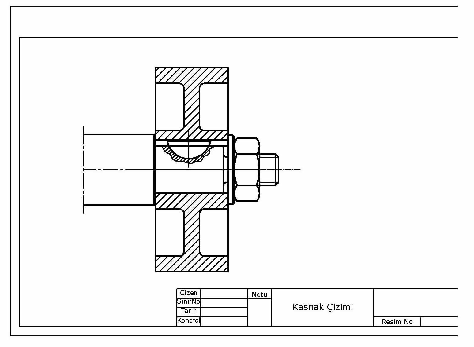
machine technical drawing pulley drawing
Drawing of a shaft-pulley connection with a half-moon key and nut

B — Stepped pulleys:

machine elements stepped pulley

Stepped pulleys are essentially two or more flat pulleys of different diameters joined together.
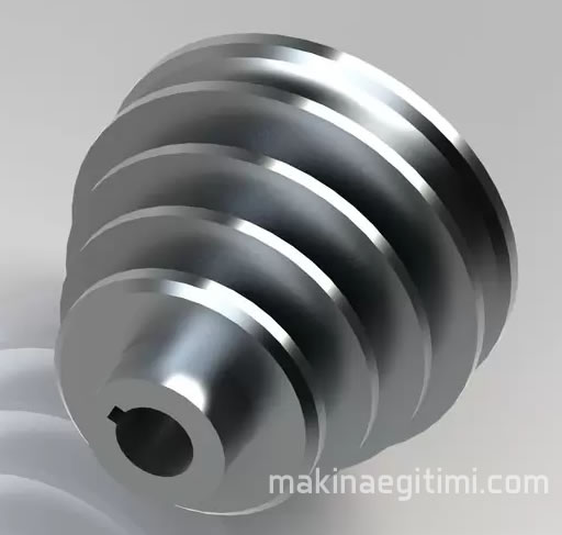
stepped graduated pulley

Stepped pulleys are also called (Graduated pulleys) or (Cone-step pulleys).

Stepped pulleys are also called (Graduated pulleys) or (Cone-step pulleys).

The sum of the opposing diameters of two mutually driving stepped pulleys is equal and constant at every step (Figure: 14). That is:
D1 + D’1 = D2 + D’2 = D3 + D’3 = constant.

If this weren’t the case, when it became necessary to change the rotational speed of the driven pulley by shifting the belt along the endless belt-pulley axis, the belt would either not fit the next step or would be too loose for it.

lathe parts headstock spindle box belt pulley
Transmission of power from the motor to the spindle via belt and pulley on a universal lathe

C — Conical pulleys:

Pulleys whose rim resembles a truncated cone are called (Conical pulleys). The taper turning angle (A) of the pulley is (12°) or (15°).
To use conical pulleys in operation, we need to place two identical pulleys opposite each other.

Conical pulleys are used where stepless transmission of small amounts of power is desired. The belt is shifted along the pulleys in the direction of the arrows, changing the rotational speed of the driven pulley.
When the belt is at the middle of the pulleys, the rotational speed of the driven pulley equals the rotational speed of the driving pulley (ignoring belt slip).

By crossing the belt on conical pulleys, motion can also be obtained in the opposite direction. Since the pulleys are conical, the peripheral speed at every point is different. For the belt not to be damaged excessively, it needs to be narrow. (A belt width of at most 60 mm is recommended.)
Conical pulleys are used mostly in the paper industry.

 GUIDE PULLEYS

When the axes of the shafts transmitting motion are not parallel, or are parallel but the power and motion pulleys are offset relative to each other, (Guide pulleys) are used to prevent the belt from slipping off. Because guide pulleys direct the belt, they are also called (Directing pulleys).

TENSIONER PULLEYS

These are pulleys used to reduce the belt’s slipping on the pulley by increasing the wrap angle
and to keep the belt continuously taut.
Tensioner pulleys are flat, idler-type pulleys.

Types of pulleys by construction and their areas of use

We can divide pulleys into two groups based on their construction:

I — Solid (one-piece) pulleys
II — Split pulleys

I — Solid (one-piece) pulleys:

Pulleys made from a single piece are called (Solid pulleys).
Because solid pulleys are easy to make, we encounter them in many places.

half-section V-belt type pulley

If mounting the pulley doesn’t present any particular difficulty and its diameter is small, it’s appropriate to make it as a solid piece.

II — Split pulleys:

If a pulley is formed by joining two pieces together, it’s called a (Split pulley).
Split pulleys are superior to solid pulleys in several respects. Specifically:
A — Split pulleys are easy to install and remove. (Suppose we want to mount a pulley somewhere on a transmission shaft, or remove the pulley that’s there. If the pulley is solid, the transmission shaft’s bearings, couplings, other pulleys, etc. would all have to be dismantled. We know how tiring and time-consuming that process is. Split pulleys, on the other hand, can be mounted or removed in a very short time without requiring any of that.)
B — Solid cast-iron pulleys with a large diameter (especially D > 1000 mm) and high peripheral speed (V > 32 m/s) can crack after casting due to residual stresses and centrifugal force. In split pulleys, however, the residual stresses after casting are negligibly small.
C — To cast very large solid pulleys, a foundry with a cupola furnace of suitable capacity and a crane setup is required.
D — Especially for large-diameter pulleys made in split form, their transport, installation, and removal are significantly easier than for solid ones.
To better understand split pulleys, let’s give a few examples according to the type of material used.

Split cast pulleys:

By “split cast pulley,” we mean pulleys that are cast from cast iron or aluminum and then machined afterward on work benches.
Cast pulleys are made in two pieces. The two halves of the pulley are joined together either through the spokes or between the spokes.

The joint through the spokes is the sturdier method, so it’s used more often.
Split cast pulleys can also be produced by casting them as a single piece and then cutting them in half afterward. (This is called “splitting” the pulley — the two halves of the pulley are cast joined together over a small area, and when this area is cut, the pulley separates into two pieces.)

The two large parts of the rim, and additionally the (D) part, which is the cast-iron section supporting the rim shown as (E), along with the dovetail female section, sit on the rim which is made of thick sheet steel. The two large parts of the rim are also joined together by (B) bolts.

Split steel pulleys:

The rim section of split steel pulleys is made of sheet steel. The belt’s sliding on the pulley generates heat. So that this heat doesn’t harm the belt and can be dissipated into the air, the thickness (Z) of the rim sheet is calculated using the following formulas.
MINIMUM = Z = D/300+2
MAXIMUM = Z = D/300+3

Important: Even though the unit of the pulley’s rim diameter (D) is millimeters, we must apply it in the formula.

Wood pulleys:
Wood pulleys are used for transmitting small amounts of power and are left outside the scope of (TS) standards. The rim section of the pulley is made by gluing together many segments so that their grain runs in opposing directions.

Wood pulleys are made in two pieces, and their attachment to the shaft is done with two or four bolts, without using a key. (When the bolts are tightened, there should be a gap between the two pieces of the pulley.)

Related Posts

Shafts, Types and Properties Shafts. Types of Shafts and Their Properties Gear Terminology and Elements Gear Terminology – Gear Elements Shaft Diameter Calculation Shaft Diameter Calculation Structure and properties of rolling bearings Rolling-Element Bearings Gear Calculation Formula Tables Gear Calculation Formulas Table How Is a Rivet Gun Used How Is a Rivet Gun Used Yaprak Yaylı ve Helezon Yaylı Süspansiyonun Farkları Differences Between Leaf Spring and Coil Spring Suspension Bearing Damage and Its Causes Bearing Damage and Its Causes
Belts & Pulleys
Share. Facebook Twitter WhatsApp Tumblr Email Telegram Copy Link

Leave A Reply Cancel Reply

Why Is It Dangerous to Rest Your Feet on the Dashboard?
How to Check Radiator Coolant
  • Contact
  • Terms of Service
  • Privacy & Cookie Policy

Type above and press Enter to search. Press Esc to cancel.