Cylindrical machine parts used to transmit force between a belt and shafts are called pulleys. According to Turkish Standards, a pulley consists of three main parts:
Parts of a Pulley

Rim

The outer surface of the pulley that touches the belt is called the (rim).
(Before Turkish Standards were established, a pulley’s rim was called the “pulley’s ring” or “pulley’s tread.”)
A pulley’s rim varies according to the shape (cross-section) of the belt used to transmit power.
The rim of pulleys using a flat belt:

On pulleys using a flat belt, the belt can slip off, especially during startup. To prevent this, the rim of flat-belt pulleys is made crowned or flanged.
(We can see the crown on a pulley’s rim by looking at the pulley perpendicular to its axis. If this crown’s radius (r) is smaller than normal, the belt’s width will be flexed excessively, shortening its life. If the pulley’s peripheral speed exceeds 20 m/s, the rim must always be made crowned.
Pulleys are used in a wide range of applications. We can find them anywhere motion and power are transmitted with belts.

The rim of pulleys using a V-belt:

On the rim of pulleys using a V-belt, grooves are cut in the shape of the belt’s cross-section.
The groove’s depth should be greater than the belt’s thickness, and once the belt is tensioned, it shouldn’t touch the bottom of the groove. The side surfaces of the groove shouldn’t be rough. Because slippage always occurs during belt transmission, and the belt sliding against a rough surface causes it to wear out quickly.
The rim of pulleys using a round belt:

The figure below shows the groove cut into the rim of a pulley using a round belt. The belt shouldn’t be pinched in its groove. If we call the belt’s diameter (d1) and the groove’s diameter (d2), we can write the relationship between them as: d2 = d1 + 0.15 • d1
Body
The body of large-diameter pulleys is spoked, while that of small ones is unspoked, or in other words, solid.
The parts that connect a pulley’s rim to its hub are called (the pulley’s arms/spokes).
The cross-sections of pulley spokes vary widely.

Cross-sections of pulley spokes (above)
Those shown as (C, E, and F) are used in large-diameter pulleys that require higher strength.

Pulley spoke types. Pulley spokes are made in three forms (above). Of these, the straight spoke, shown as A, is the most commonly used.
In cast-iron pulleys, stresses form in the pulley after casting. This is because, due to the difference in thickness, the pulley’s spokes cool later than the pulley’s rim and hub. These stresses (especially in large-diameter pulleys) can cause the pulley to warp, and in straight-spoked ones, can even cause the spokes to break.
To render the post-casting stresses harmless, the spokes should be made curved, as in (B), or S-shaped, as in (C) (picture above).
Making pulley spokes this way provides the spokes with flexibility. Post-casting stresses lose their effect over time. For this reason, pulleys that need to be very precise should be left to sit for at least three months after casting before being machined. This way, the pulley warps as much as it’s going to before machining, and doesn’t change shape after being machined.

Hub
The ring-shaped middle section of the pulley that fits onto the shaft it will be mounted on is called the pulley hub.
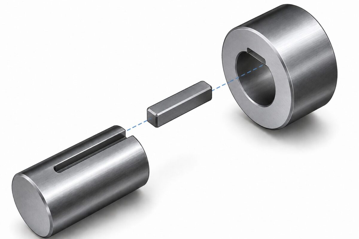
Pulleys are generally attached to the shafts they’ll transmit motion to with keys. For this, if the taper is to be on the keyway, the upper part of the keyway is prepared with a taper of 1:100.

The section of the shaft that will be joined to the pulley is turned either cylindrical or tapered, with a taper of 1:20. On tapered shafts, a key together with a draw-off screw and a nut completes the joint.
To make molding easier for pulleys produced by casting, the pulley pattern is prepared with a taper of 1:50 … 1:30 on both sides of the outer section where the pulley body meets the hub.
We can calculate a pulley’s (G) wall thickness and (L) hub width with the following formulas:
Minimum: G1 = 0.3 d + 10
Maximum: G2 = 0.5 d + 10
Minimum: L1= 1.2 d
Maximum: L2 = 1.5 d
Important: In the formulas above giving the (G) hub wall thicknesses, the unit for (d), the diameter of the hole the shaft passes through, is millimeters.
Related Posts