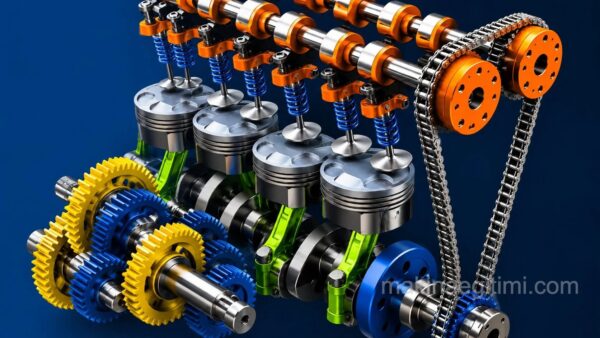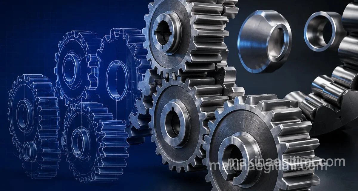
Gears are among the most widely used machine elements. Types of gears by the arrangement of their shaft axes:
Parallel-Axis Gears:
Intersecting-Axis Gears:
Gears With Neither Parallel Nor Intersecting Axes:
Parallel-Axis Gears
Spur Gears
The most common type of gear is the cylindrical spur gear. Their teeth are straight and parallel to the shaft axis.
Advantages of spur gears:
Spur gears are preferred for reasons like low manufacturing cost, not transmitting axial force, and being easy to maintain.

Disadvantages of Spur Gears:
They run noisily. Also, a high reduction ratio can’t be achieved with a single spur gear pair. To achieve a high reduction ratio, these gear sets need to transmit drive in several stages.
Helical Gears
These are cylindrical gears just like spur gears. What sets them apart from spur gears is that their teeth are helical.
The most important advantage of these gears is that, for the same size, they can carry higher loads and can run more quietly and at higher speeds than spur gears.

In helical gear pairs, since the neighboring tooth engages the mating gear before the previous tooth disengages, they run more precisely and quietly.
In a helical gear pair, if one gear has a right-hand helix, the other has a left-hand helix.
The biggest disadvantage of these gears is that they transmit axial force to the shaft and bearings.
For detailed information
See also: Helical Gears

Double Helical Gears
Double helical gears are two helical gears on the same axis, manufactured as a single piece.
If one of these gears is cut with a right-hand helix, the other is cut with a left-hand helix.
This way, the axial forces — the biggest disadvantage of helical gears — cancel each other out, so they don’t transmit axial force to the shaft and bearings.
These two helices don’t meet in the middle; there is a small gap between them.

Herringbone Gears
These are double helical gears with no gap in the middle, meeting at the apex. They run more precisely, but since special cutters are needed to manufacture them, their production cost is high. They also require more careful maintenance than other gears.

Sprocket Gears (Sprocket & Chain)
Sprocket gears are used where the distance between shafts is long and rotary motion needs to be transmitted within the same plane.
High torque can be applied to sprocket gears, but they can’t be used at high speeds and are quite noisy. Another disadvantage of these is that the chain sags on the slack side. Tensioner sprockets are generally used to remove this sag.
For sprocket gears, defined as ANSI B29.1 in American standards, there are many standards under the DIN norm. However, the most commonly used standards are DIN 8187 and DIN 8188
A chain supplied to DIN 8188 cannot be used together with a sprocket supplied to DIN 8187. The chain and sprocket must be sourced together, and the DIN norm must always be specified when ordering.
The hub portion of a sprocket is supplied as raw stock, and the shaft bore and keyway are machined afterward to match the application’s dimensions.

Related Post Types of Sprockets, Lesson
Types of sprockets. Silent chain sprockets. Roller chain sprockets. Block chain sprockets. Standard chain sprockets. Pintle chain sprockets.
Timing Gears
These gears are used not for transmitting torque but for synchronizing position. Their best-known application is synchronizing the motion taken from the crankshaft, via the camshaft, in vehicle engines. Since these gears don’t transmit torque, their tooth depth is extremely shallow.
These gears are used together with timing belts. The timing belt is also known as the timing belt.
The most important thing in this pairing is that there must be no slippage whatsoever between the belt and the pulley. In this system, timing gear speed can reach up to 10,000 rpm. Since they aren’t expected to transmit torque, belt tension is kept very low, giving them a long service life.
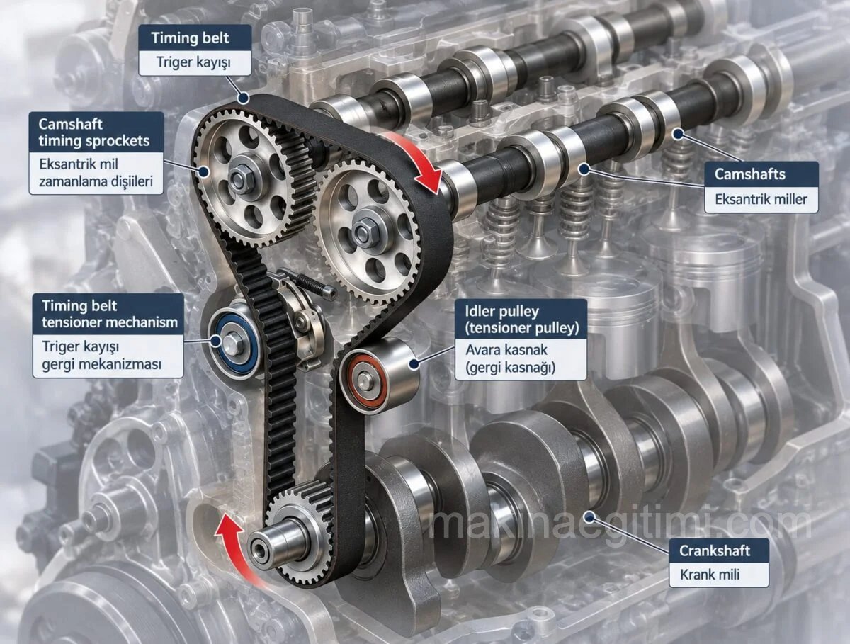
However, since it’s very important to keep the teeth on the belt in constant contact with the teeth on the pulley, an idler pulley is used on the slack side if needed. (Above)
Planetary Gears
Named after the sun and the planets orbiting it, this system is called Planetary Gears. A fixed ring gear, and the pinion (planet) gears orbiting inside it that transmit low speed and high torque to the output shaft, form the basic operating principle of this gear set.
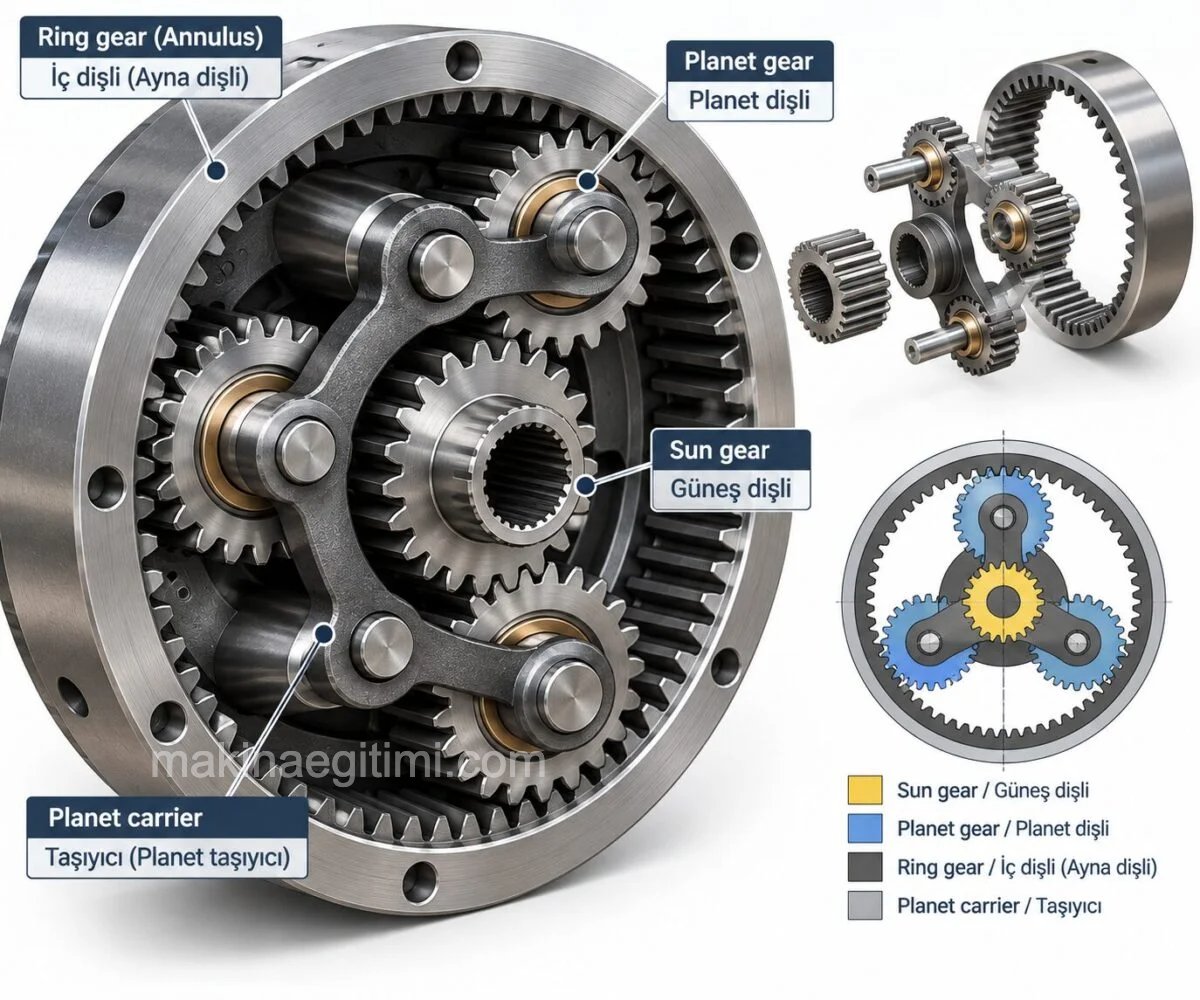
ADVANTAGES OF PLANETARY GEAR SETS
They provide high reduction ratios and high torque transmission. Their efficiency is high (generally running at about 97% efficiency). Compared to the amount of torque they transmit, they have a small volume and compact structure. The loads within the gear set are distributed evenly.
Another advantage of planetary gears is their low elastic deformation.
The disadvantages of planetary gears are the heavy loads placed on the bearings, their more complex design, and difficult maintenance.
Intersecting-Axis Gears
These are types of gears whose axes intersect each other. Among themselves, they’re manufactured in the types listed below.
Straight Bevel Gears
These are straight bevel gears whose axes intersect at any angle.
The most commonly encountered bevel gears have a 90-degree angle between their axes.
These gear pairs are designed so that the extensions of their pitch cones meet at the same point. When one of the gears is replaced, the other must always be replaced too.

Straight bevel gears are preferred at speeds below 1000 rpm, for moderate loads, in places where noise isn’t very important.
Spiral Bevel Gears
In these gears, unlike straight bevel gears, the teeth are spiral-shaped. Since the spiral angle can be set at any angle relative to the axis of rotation, 2 or more teeth can be in contact at the same time, transmitting force through two or more points. Compared to straight bevel gears, they can transmit much larger forces at much higher speeds. If the spiral bevel ring gear has a right-hand helix, the pinion gear must have a left-hand helix. (Figure below)
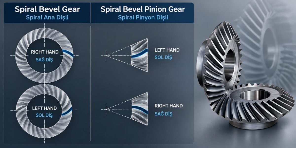
Spiral bevel gears are used where speed exceeds 1000 rpm, large loads need to be transmitted, and quiet operation is required. If the peripheral speed of these gears will exceed 40 m/s, the teeth must always be ground.
Where Spiral Bevel Gears Are Used
The gears found in a car’s differential, known as the ring and pinion, are spiral bevel gears. (below)

Besides this, spiral bevel gears are used in: gear reducer housings, construction and heavy equipment, drilling machines, forklifts and other lifting equipment, tractors and trenching machines (agricultural machinery in general), textile machinery, various door and duct mechanisms, and machine tools.
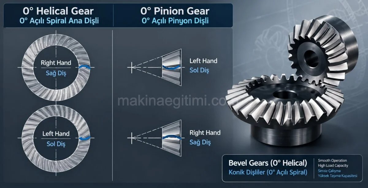
Zero-Spiral-Angle Bevel Gears
These are similar to spiral bevel gears. However, their spiral angle is zero degrees.
Gears With Neither Parallel Nor Intersecting Axes
These are gears whose axes lie in different planes.
They’re named based on the position of the pinion gear’s axis relative to the ring/main gear it works with.
Worm and Worm Gear
Among non-intersecting-axis gears, the worm and worm gear are the most widely used. Since these gears can run vibration-free, quietly, at very large reduction ratios, and at very high speeds, they’re the primary type of gear used, particularly in gear reducers. (below)

In a worm-worm gear pair, the worm’s axis is positioned tangent to the gear.
One of the biggest advantages of this gear type is that, if the lead angle is less than 5°, these gears can operate as self-locking. That is, if rotary motion is applied via the worm gear rather than the worm, the worm will not turn backward. This eliminates the need for a brake in some applications (for example: a wheeled vehicle being driven uphill, with a worm-gear reducer with a tooth angle less than 5° at the motor output, will not roll backward once the motor stops, even without a brake)
Hypoid Gears
These are very similar to spiral bevel gears. Their difference from spiral bevel gears is that the pinion gear’s axis is offset from the ring gear’s axis by a certain distance. As this distance increases, the operating range shifts from the hypoid gear operating range into the spiroid gear operating range.

These gears are quieter than spiral bevel gears and have a longer service life. Their shock resistance is high.
Spiroid Gears
Spiroid gears are used where high torque transmission is involved and drive needs to be transmitted at a right angle. These gears are among the compact types of gears that run quietly and don’t have a large volume relative to the torque they transmit. Another advantage is that they’re easy to disassemble and reassemble. The reduction ratios they provide can range from 1:3 up to 1:400. Their shock resistance is high.

The biggest advantage of spiroid and hypoid gears over worm gears and spiral bevel gears is that, due to the offset between their axes, more teeth are in contact with each other during drive transmission, making higher torque transmission possible.
Rack and Pinion Gears
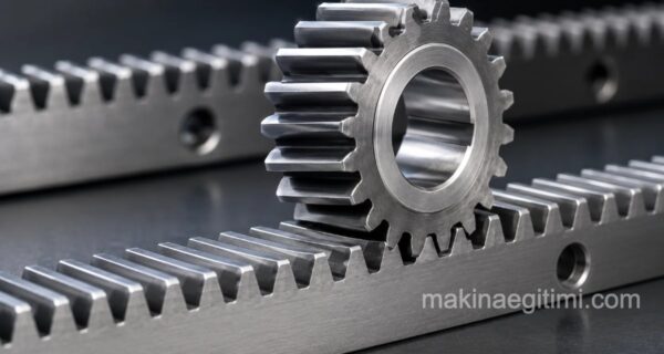
Rack and pinion gears are the most commonly used mechanism for converting rotary motion into linear motion. The gear (pinion) is usually a spur gear, though it can also be manufactured as a helical gear. The pinion is designed according to normal gear design principles, while the rack is manufactured to the desired length to match the pinion’s module.
Related Post Rack Gears and Their Applications
What is a rack gear. What is its purpose. Where is it used. Applications of a rack gear. Explained with examples.
Related Questions
In spur gears, when two teeth contact each other, the entire tooth face engages and disengages at the same instant. This sudden contact and separation produces a distinct impact sound, unlike the gradual engagement seen in helical gears.
This gear pair works by having a screw-shaped element engage the mating gear at a right angle, and thanks to this design, it can transmit power between shafts that are neither parallel nor intersecting in the same plane. This solves a specific layout requirement that other gear types can’t accommodate.
Related Posts