

Transfer Molding
Transfer molding is mostly used to produce workpieces with thin walls or irregular cross-sections, with cores, or with metal inserts placed inside them. Transfer molding is done on special dual-piston presses. One of the pistons serves to close the mold. There are types of these presses that press from top to bottom, from bottom to top, and from the side.
Transfer Molding Presses
The figure below shows a simple, retractable transfer molding press providing a compressive force of up to 100 tons.
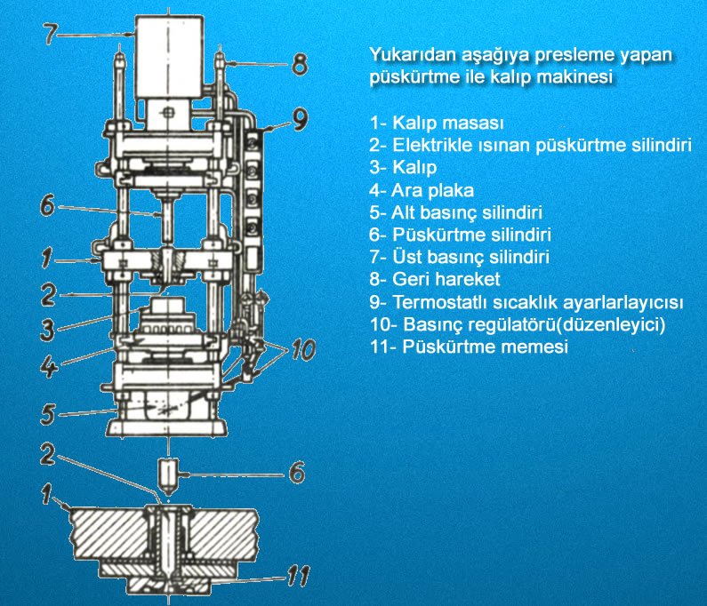
The distinguishing feature of this press is an intermediate plate (4) that can be adjusted vertically between the worktable (1) and the compression cylinder (5). The intermediate plate holds the transfer cylinder (2) and the electric heating unit. The mold (3), i.e. the tool, is attached to the worktable. This way, the mold is under the influence of the compression cylinder (5) mounted below the worktable. (In other words, the closing force required to close the mold is provided by the worktable.) After enough molding material has been pushed into the mold via the transfer cylinder, running the press moves the worktable upward.
The mold halves close together. After this, the softened plastic material is transferred into the mold by the pressure piston, which is driven under pressure inside the transfer cylinder. During this, about 1/5 of the force generated at the transfer piston is consumed in keeping the mold in the closed position.

In transfer presses that press from bottom to top, the transfer piston is connected to a cylinder mounted on the press’s base. (figure above) The transfer stroke is set upward; the mold halves are attached to the stationary intermediate plate or to the closing cylinder above. The transfer cylinder (1) is fitted inside the mold. The feed happens directly at the top of the piston. In this case, the plastic material used consists of pre-shaped tablets held against a preheating step for this purpose. Otherwise, the feed process runs into many difficulties.
Transfer Molding Tooling
1- Split-Jaw Molds
In this type of mold, the mold cavity is placed inside a tapered ring (with a taper of 1:5) and is formed by removable split jaws. The tapered ring is often fitted with an electric heater. The molding and transfer nozzle is machined into the jaw or into a special punch. Applications related to machining the runner cavity and the transfer nozzle into the jaw are shown in the figure below.
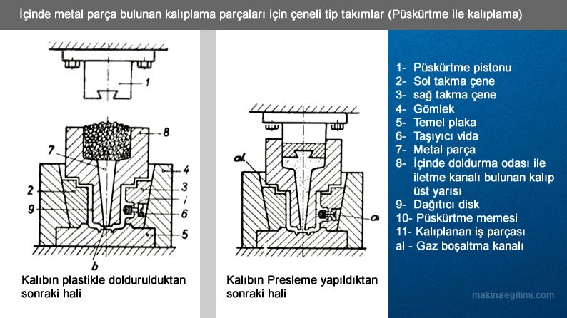
In this type of mold, the mold cavity consists of the following parts: two half-jaws (2, 3), a metal part (i) attached to the screw (6) in jaw (3), the upper mold half (8), and the base plate (5). The transfer nozzle is machined into the upper half of the mold. A dovetail channel is cut into the transfer piston (1) to clean out plastic that hardens in the transfer nozzle. As the punch makes its return stroke, the plastic breaks off at its weakest cross-section, that is, near the distribution disc (b). The plastic piece that comes out along with the punch is then pushed to the side and removed.

A split-jaw type mold where the plastic filling chamber is located within the jaws (transfer molding)
In this type of construction, side forces generated by the pressing pressure try to pull the jaws open. This naturally leads to the formation of flash, which is undesirable. Bolts 14 and 15 prevent the core from shifting sideways. The runners are cut for the jaws. This mold transfers a fairly complex four parts at the same time. The disadvantage of such designs is that the jaws can flex under high pressing pressure. For this reason, non-split transfer cylinders should be used for large molds and high pressing pressures.
The figures below show two separate mold designs that allow four parts to be pressed simultaneously, with non-split transfer cylinders.
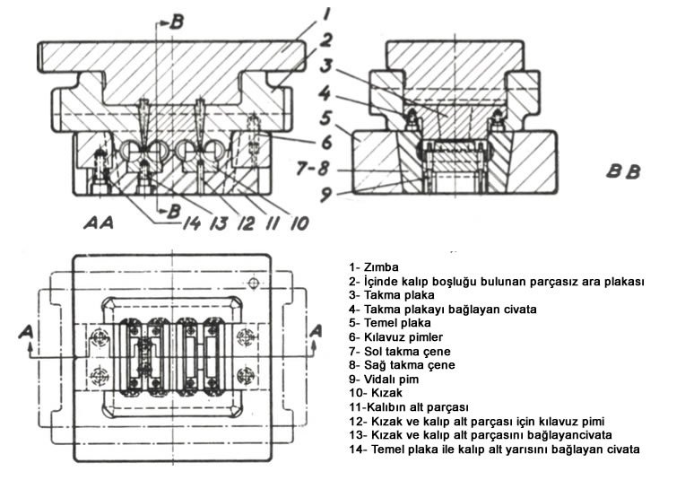
A split-jaw type mold with a non-split mold cavity (figure above)

A transfer molding die prepared for a press that presses from the bottom upward. (figure above)
Left: the mold ready for transfer.
Right: the mold in the open position at the end of the operation, with the workpiece ejected.
2- Molds with Hydraulically Provided Clamping Force
In the molds introduced so far, the pressing pressure or pressing force was resisted by the jacket surrounding the mold cavity. Because of this, these molds are prone to flexing outward to some degree, which is a drawback, and a certain amount of flash forms at the mold’s parting line. Flash also occurred when the mold cavity was made larger than necessary. To prevent this problem, the mold must be closed before the transfer process begins. The closing is done by a hydraulic cylinder. It’s easy to see that the closing pressure required for this purpose must be greater than the injection pressure, because the closing pressure creates a hydrostatic pressure inside the mold. Closing pressure is applied not only from below, but from above and from the side as well.
Special mold constructions are used in cases where the closing pressure is applied from the side. (Figure 345) Figure 59 shows a mold placed in the lower half of the transfer cylinder. The upper half of the mold is attached to the bridge of the closing cylinder. This mold is designed to produce six workpieces in a single transfer operation. The mold cavities are placed at equal distances from the center and at equal intervals. Steel insert parts are used for the mold cavities. The connection between the mold cavities and the transfer cylinder is provided by transfer channels machined into the part. If a special press machine isn’t available, the hydraulic closing pressure can also be provided by the normal transfer pressure.

The same is true in the transfer press mold example above. In this mold design, (the mold is kept closed by the transfer pressure itself). The mold is essentially made up of three main sections:
1. The upper section (1—5), which contains the transfer piston and is connected to the working cylinder.
2. The intermediate part (6—11, 19, 20), which carries the transfer cylinder and transfer nozzle.
3. The lower half of the mold (12-18)
When the mold opens upward, the middle part rises along with it, making it possible to eject the pressed workpiece and clean the inside of the mold. For safe operation, the closing force generated by the hydraulic pressure needs to be kept as high as possible. Additionally, the closing force needs to be kept large so that the upper and intermediate parts press against the lower part.
The mold can only remain closed on its own if the cross-section of the punch (1) is larger than the sum of the cross-sections of the pressed workpieces perpendicular to the pressing direction.
Use of Low Pressure
Transfer molding (blow molding) is a method that operates at lower pressures than injection molding.
Hollow Part Production
This method is especially preferred for producing hollow plastic parts, such as bottles and cans.
Shaping with Air
In the process, a molten plastic parison is first placed in the mold, then inflated with pressurized air against the mold walls.
Related Questions
In this method, the molten material is transferred into the mold at high pressure and speed. This high pressure ensures the material fully fills even thin, narrow cavities, making it possible to produce thin-walled, complex parts.
One piston keeps the mold tightly closed, while the other pushes the molten material into the mold cavity. This division of tasks guarantees the mold fills in a controlled way without opening under the material’s pressure.
Related Posts
 Professional 3D Scanners and Their Applications
  3D Printer Applications Today and in the Future
  Laser Cleaning: Removing Rust, Dirt, and Grease
  Operations Performed on a Lathe
  How Are Washers Made
  Gear Manufacturing Methods
  Heat Treatments Applied to Cast Iron
  What Is Submerged Arc Welding, How Is It Done