

In this article we cover the taper types accepted as standard in industry, the mathematical relationship between taper and slope, worked example calculations, and the methods used to measure and check a finished taper. We also explain, with pictures, how taper turning is done on a universal lathe and what the taper turning methods are.
The geometry formed when the diameter of a rotating part changes uniformly along its axis is called a taper, and the process of producing that geometry on a lathe is called taper turning. Calculating the taper correctly and verifying it after machining determine the quality of the job just as much as the method you choose.
Standard Taper Types Used in Industry
In turning work you frequently need tapers produced to defined standards rather than to arbitrary angles. The reason is the need for interchangeable mating surfaces that fit together across different machines and tools.
The standard tapers most commonly met in industry are
- the Morse taper,
- the Brown & Sharpe taper, and
- the Jarno taper.
The Morse taper is used on machines for chucks, drill shanks, spindle noses and centres, while the Brown & Sharpe taper is preferred more for arbor, spindle and cutter shank connections on milling machines. Besides these standard tapers there are also special tapers produced with different taper ratios and angles according to the intended use.
For example, a wide angle of 120 degrees is used for the protective countersinks of holes, 60 degrees for centre drills, and a very narrow angle of about 3 degrees for the Morse tapers used on machine tools. The narrower the angle, the more the taper tends to “lock”, which makes it suitable for mounting and centring applications. As the angle widens, the taper becomes better suited to applications where self-locking is not wanted, such as a bolt head or a rivet head.
The Basic Elements of a Taper
Five basic dimensions and ratios are used to define a taper: the taper ratio, the taper length, the large diameter, the small diameter and the taper angle. The taper ratio is a numerical value showing how quickly the part gets thinner or thicker. The slope is equal to half the taper ratio, because the difference in diameter is distributed symmetrically to both sides of the part.
How Are Taper and Slope Calculated?
Taper is found by dividing the difference between the large and small diameters by the taper length.
Slope is then calculated by taking half of that ratio, because slope expresses a one-sided angle.
In practice, taper is usually expressed in the form “1:x”. The value of x shows the length needed for the diameter to change by 1 millimetre. If the taper is 1:20, for instance, it means the diameter of the part decreases (or increases) by 1 millimetre for every 20 millimetres of length.
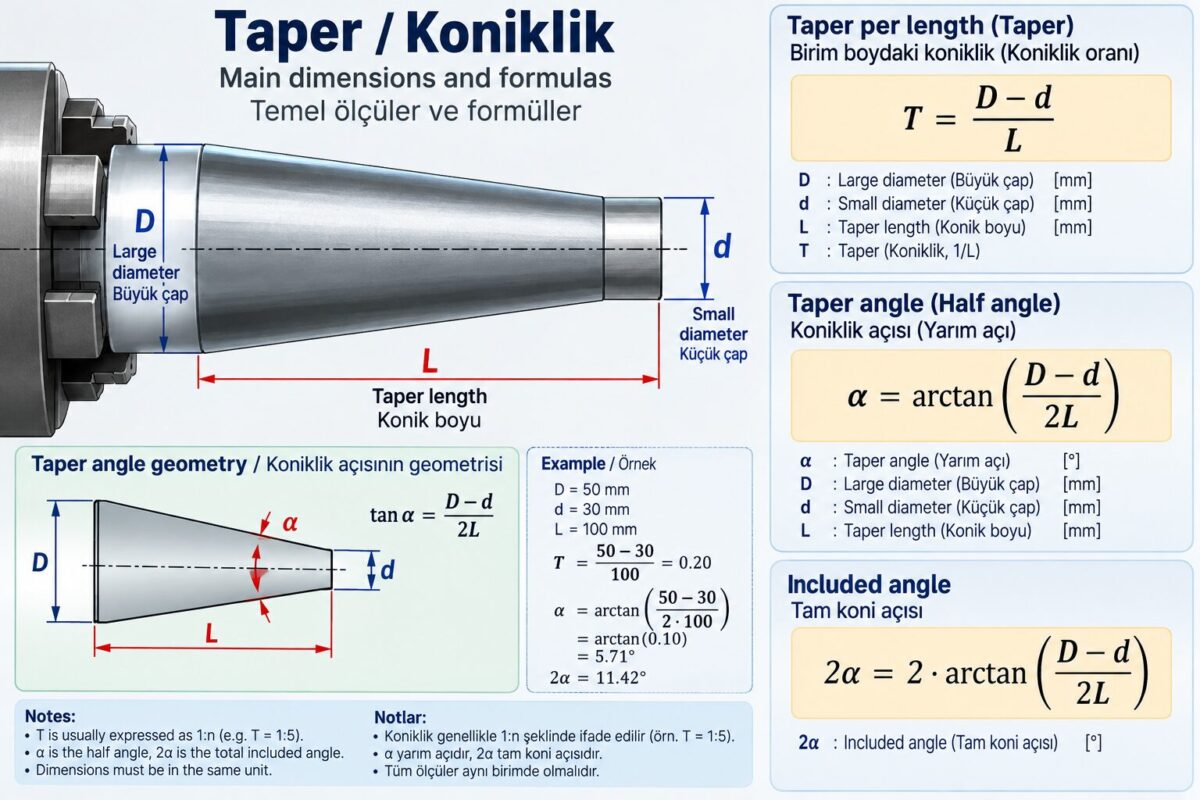
Example 1: Let us find the taper and slope of a part with a large diameter of 60 mm, a small diameter of 46 mm and a taper length of 70 mm.
The difference in diameter is 60 − 46 = 14 mm. Dividing this difference by the taper length gives 14/70 = 1/5, so the taper is approximately 1:5. Since the slope is half the taper, it comes out as 1:10.
Example 2: On a part with a taper of 1:40, a taper length of 80 mm and a large diameter of 64 mm, let us find the small diameter.
From the taper formula, the small diameter is found by subtracting the taper ratio multiplied by the taper length from the large diameter: 64 − (80/40) = 64 − 2 = 62 mm.
These two examples show how to find the taper from dimensions given at the design stage, and how to complete a missing dimension from a required taper at the production stage. Both directions are calculations you meet often in the workshop.
What is taper turning?
A shape whose diameter changes uniformly as a function of position along an axis is called a taper.
The process of uniformly changing the diameter of a rotating part along its axis, on a lathe, is called taper turning.
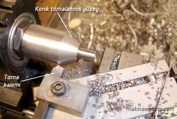
Taper Turning Methods
Taper turning can be done in 3 different ways:
- Taper turning by swiveling the compound rest on universal lathes
- Taper turning by the tailstock offset method
- Taper turning with a taper turning attachment
The taper turning methods discussed here apply to universal lathes. Which method you use can vary based on the length and condition of the workpiece, your workshop and equipment conditions, or your own experience.
On CNC lathes and with copy-control systems, both tapers and other various profiles can be produced quite simply, since there is no need to change the machine’s physical setup.
Taper Turning by Swiveling the Compound Rest
(Compound rest method) In taper turning by adjusting the compound rest, the compound rest is swiveled, using its graduated scale, to the taper’s setting angle. Feed is applied by hand.
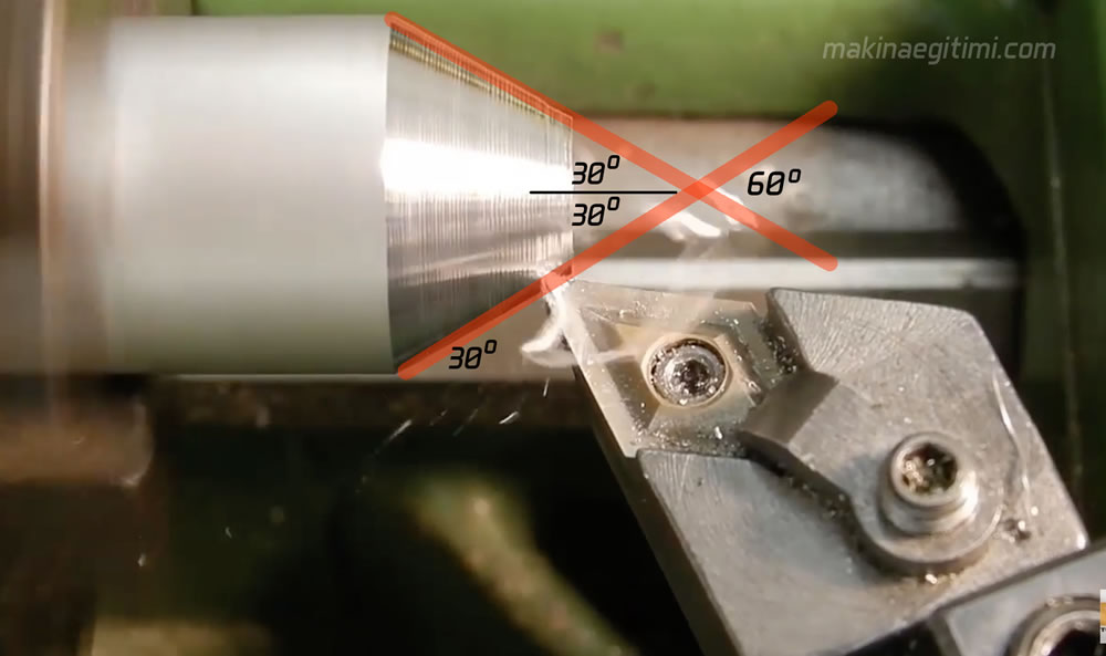
The standard angles used in taper turning. In the example above, 60 is the taper angle, and 30 is the setting angle (the angle to give the compound rest).

The setting angle given to the compound rest is half the taper angle. For example, if the taper angle is 60 degrees, the angle given to the compound rest is 30 degrees.
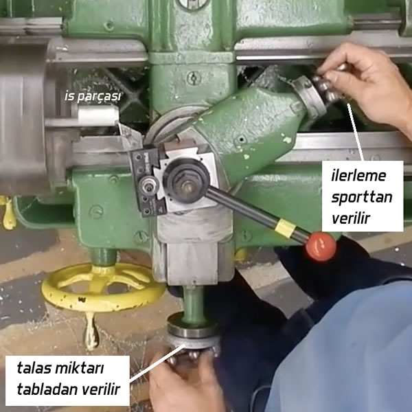

We also have to think about workplace safety while swiveling the compound rest for taper turning. In a position like the one shown, our left hand is at risk.
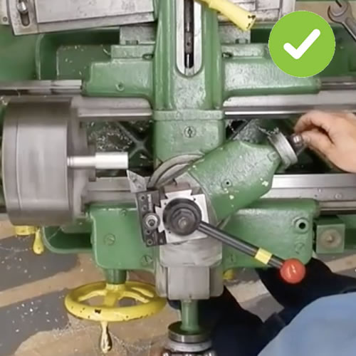
The correct positioning, without putting our workplace safety at risk, should be as shown here.
ADVANTAGES: Since it does not require any extra attachment, this method is easier to apply than the others.
DISADVANTAGES: This method can only be applied to short tapers, since the compound rest’s possible range of travel is limited. Also, since feed can only be given manually, the surface finish will be relatively rough.
The video above shows how taper turning by swiveling the compound rest, one of the taper turning methods, is done.
Taper Turning by the Tailstock Offset Method
(Tailstock set-over method) For taper turning by this method, the tailstock has to be offset from the spindle axis.

In the tailstock offset method, how much offset is needed is worked out from a simple similar-triangles relationship. If the taper length is equal to the full length of the part, the offset is found directly from half the difference in diameter together with the ratio of taper length to part length. If the taper is shorter than the whole part, the same logic is applied in proportion to the part length.
Example: A taper 300 mm long, running between diameters of 35 mm and 25 mm, is to be turned on a part 600 mm long. Let us find how far the tailstock has to be offset.
The difference in diameter is 35 − 25 = 10 mm. This value is multiplied by the part length and divided by twice the taper length: (10 × 600) / (2 × 300) = 6000/600 = 10 mm. So the tailstock has to be offset by 10 mm.
You should also check separately whether the offset found by this calculation stays within the maximum offset the machine’s tailstock allows. If the limit is exceeded, this method cannot be used and you have to switch to an alternative such as swiveling the compound rest or using a taper turning attachment.
With the tailstock offset method, long tapers can be turned between centres. For this, the tailstock can be offset from the main axis of rotation by at most 2 per cent, or 1/50, of the workpiece length.
The tailstock offset method is useful for long parts. Because the feed can be applied automatically, the surface finish is clean. In this method the centre does not seat properly in the centre holes, so a ball-ended centre should be used.
If the tip of the turning tool is set on the axis, dimensional and form errors occur that are more pronounced at small diameters.
Drawbacks of the tailstock offset method
- Tapers become harder to machine as the diameter grows.
- Because the part is held from its ends, tapers cannot be cut in bores.
- The centre setting is not precise.
- The amount of tailstock offset is limited.
- Because the centre does not seat well, there is a risk to the job.
Swiveling the Compound Rest
Taper turning by swiveling the top compound rest is the method preferred for machining short tapers with steep angles.
Tailstock Offset
The tailstock offset method is used for machining long tapers with shallow angles between two centres.
Taper Ratio Calculation
In taper turning, the taper ratio is calculated by dividing the difference between the large and small diameters by the taper length.
Taper Turning With a Taper Turning Attachment
Taper turning with a taper turning attachment can be done with high precision. When the system is being set up, the cross-slide feed screw is disengaged and the attachment is clamped to the lathe bed. The guide bar is then swiveled to the setting angle a/2 and the guide sleeve is tightened.

When the lathe is put into automatic feed, the saddle travels longitudinally while the tool cuts a taper following the slope set by the guide bar. For internal taper turning, the guide bar is swiveled the other way.
Video: taper turning with a taper turning attachment
Measuring and Checking Methods for Tapered Parts
Even when a taper has been calculated and turned correctly, confirming that the result really is the size you wanted is a separate step. Three different methods are widely used for this check.
Measuring with a vernier caliper: The large and small diameters of the taper are measured separately, and you check whether the ratio of the difference to the taper length matches the required taper value. On a part with a taper ratio of 1:50, for example, the diameter is expected to change by 1 mm over every 50 mm of length.
Checking with a gauge: The gauge used for internal tapers has two limit lines on its large-diameter end. If the gauge enters the taper as far as the space between those two lines, the taper is correct. On an external taper gauge the small-diameter end is stepped, and if the gauge goes on as far as the space between the stepped faces, the taper is right. This method gives a quick go/no-go check in series production.
Precision checking with a dial indicator: For work needing higher accuracy, the top edge of the workpiece is brought level with the help of a sine bar and gauge blocks. In this setup the height of the gauge blocks is calculated by multiplying the length of the sine bar by the sine of the taper angle. Once the workpiece has been levelled this way, the tip of the dial indicator is run along the part. If the needle does not move at all, the taper setting is exact; if it moves, you can work out which side of the part is over or under size and correct it.
In this article in the manufacturing processes category we answered the question of what taper turning is, explained with pictures how taper turning is done on universal lathes, and gave information about the taper turning methods. You can also take a look at the recommended taper turning videos below. See you in our next articles.
Recommended Videos on Taper Turning


Related Questions
On CNC machines the movement of the tool is programmed under computer control, so there is no need to alter the physical setup of the machine to produce a tapered surface. On universal lathes, manual adjustments such as swiveling the compound rest are required.
The choice depends on the length of the part to be machined, the equipment available in the workshop and the operator’s experience. Different methods give a more practical result over different ranges of length and angle, so the choice is made to suit the situation.
Taper expresses the total change in diameter of the part, while slope expresses half of that change, that is, the deviation on one side of the axis only. That is why the slope value is always half the taper value.
The Morse taper is widely used for machine and centre mountings, while the Brown & Sharpe taper is common for arbor and cutter shank connections on milling machines. The choice is determined by the standard of the machine and tooling in use.
No. The offset found has to stay below the maximum offset the machine allows. If that limit is exceeded, the compound rest method or a taper turning attachment should be used instead.
Checking with a gauge gives a fast but coarse verification and is generally preferred in series production. Checking with a dial indicator, using a sine bar and gauge blocks, offers a far more precise measurement and is used on work that demands accuracy.
The most common mistake is confusing the slope value with the taper value. Mixing up whether the difference in diameter should be divided by the taper length or by twice the taper length leads to a wrong angle or a wrong offset.
Related Posts
 Work Instructions for a Surface Grinding Machine
  Shaper – Parts and Types
  Hand Tools – Types of Wrenches
  Work Instructions at a Drill Press
  Balancing a Grinding Wheel. Grinding Wheel Balancing
  Knurling. The Knurling Process on a Lathe
  Metric and Whitworth Thread Systems
  Causes of Cutting Tool Wear in Milling