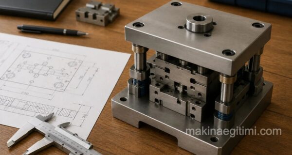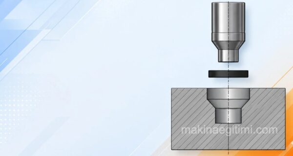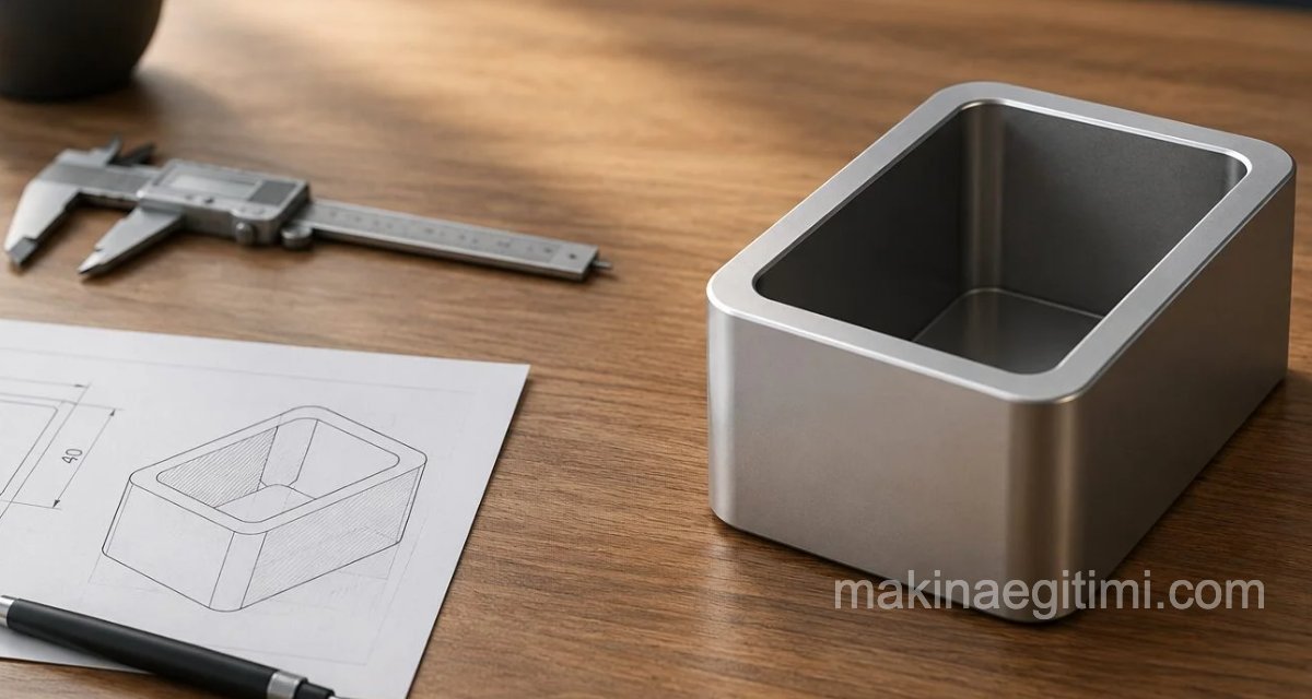
Die designers generally don’t like producing many square or rectangular containers with unsuitable depths, because drawing deep square or rectangular containers is quite difficult and costly.

Square and rectangular drawing dies are used to draw bathtubs, sink basins, gas cans or tanks, engine oil pans, refrigerator freezer trays, and many similar parts. Even though there are many use cases, cylindrical drawing is preferred over square or rectangular drawing because die design is easier and cheaper, and tearing and wrinkling are less common during drawing. The figure below shows a schematic rectangular draw and its main dimensions.

Corner Drawing
When drawing square and rectangular containers, compressive, bending, drawing, and again bending stresses occur in sequence at the corner radii of the part being drawn (left side of the figure below).

Just as with cylindrical drawing dies, a blank holder is used in square and rectangular drawing dies to prevent wrinkling that may occur at the corners during drawing. However, the holding force must be adjustable based on the container material thickness, drawing stress, and die radius. If the draw depth and holding force are too great, tearing zones occur around the base of the drawn container, as seen on the right in the figure above.
Percentage (%) Reduction Ratio Between Corner Radii
In square and rectangular drawing, wrinkling occurs at the corner radii of the drawn container. For this reason, a larger corner radius is chosen for the container to be drawn, and greater blank-holder force is applied. Additionally, to prevent compression during drawing, the corners of the sheet material undergoing drawing are relieved appropriately (see the figure below).

The percentage (%) reduction ratio between corner radii is found with the formula below.
% Reduction ratio = (R – r / R) x 100
R = Corner radius of the sheet material to be drawn, mm
r = Corner radius of the drawn container, mm
In rectangular and square drawing, for the first draw the percentage reduction ratio between corner radii should never be at or above 50%. However, for the first draw of rectangular and square containers, the percentage reduction ratio applied between corner radii is taken to be around 30%.
In staged (multi-step) drawing of rectangular and square containers, the percentage (%) reduction ratios between corner radii should be taken as 25% less than the previous radius ratio, just as in cylindrical drawing.
Wrinkle Flow Ratio
Wrinkling that occurs at the corner radius profiles of square and rectangular containers is quite significant. Wrinkling, which increases in intensity at the corner radii, migrates toward the side walls. The reflection of this wrinkling from the drawn shape onto the container’s side wall is called the wrinkle flow ratio. The figure below shows how wrinkling that occurs at the corner profile of the drawn container is reflected onto the side walls.

If the wrinkling intensity is too great and reflects onto the side walls, notches are cut into the side walls of the container material to be drawn. During drawing, these notches keep the sheet material to be drawn under tension. This equalizes the distribution of the wrinkle flow ratio that would otherwise occur around the shape of the container during drawing. If tearing occurs in the notched area, a beading (depression) operation is applied to the side walls of the container material.
Calculating Container Dimensions in Rectangular and Square Drawing
When drawing square and rectangular containers, compressive stresses occur at the corner radii of the part to be drawn, while drawing (tensile) stresses occur on the side walls. In containers with small corner radii, the compression occurring at the corner surfaces also causes compression in the material flow that occurs on the side walls due to drawing.
The compressive stress that occurs at the corner radius surfaces depends on the ratio of the corner radius to the drawn container’s width (r/w).
The bending stress and wrinkling resistance of the material being drawn varies depending on the ratio of the sheet material thickness to its blank width (T/W). The draw factor based on the ratio of sheet material thickness to blank width is given in the table alongside.

For single-operation drawing of rectangular or square containers, the ratio of depth to drawn container width (h/w) values are given in the table below.
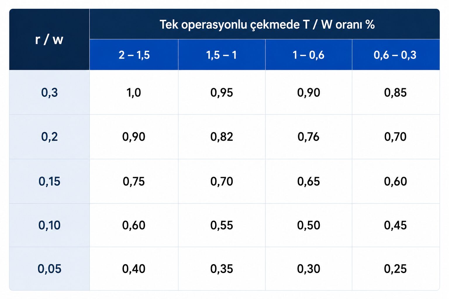
The ratio of draw depth to container width varies depending on the ratio of corner radius to drawn container width (r/w) and the ratio of sheet material thickness to blank width (T/W).
The number of stages in which a shaped container can be drawn is affected by the ratio of draw depth to container width (h/w) and the ratio of the inner-surface corner radius to container width (r/w). In the figure alongside (Figure 5), the areas A, B, and C belonging to the second curve show that drawing operations within them can be done in a single operation.
Positions within areas D, E, and F on the first curve indicate that the drawing operations can be performed in two or more operations. Drawing operations at positions between the first and second curves are shown to be achievable in a single operation.
For draws falling within areas A, B, and C, the ratio of sheet material thickness to the width of the part to be drawn (T/W) cannot exceed 0.6%.

For draws falling within areas D, E, and F, the ratio of sheet material thickness to the width of the part to be drawn (T/W) cannot be taken smaller than 2%.
Each area in the figure above describes the characteristics of the containers to be drawn. Area A is used for drawing containers where the inner-surface corner radius is small and the r/(w-h) ratio should not exceed 0.17. When drawing this type of container, the compressive stress occurring at the corner radius surfaces reflects very little onto the side walls. For this reason, the draw height on the side walls is kept constant. The blank dimensions for draws falling within area A are shown in the figure below accordingly.

Area B is applied for draws with medium-sized inner-surface corner radii, where r/(w-h) = 0.17 – 0.4. However, in some cases, the compressive stress occurring at the corner radius surfaces can cause tearing near the base surface of the drawn container.

Figure 7-a and Figure 8 show the corner radius profiles in draws falling within area B.
Explanation of the symbols in Figure 7:
h = Draw depth of the drawn container, mm
rz = Punch nose radius, mm
r = Die corner radius, mm
R = Corner radius of the part to be drawn, mm
Area D is applied for draws where the ratio of draw depth to width (h/w) is greater than 0.65 and the corner radius profile resembles Figure 7-b.
Area C is applied for draws with medium-to-large corner radii, where the r/(w-h) ratio should be greater than 0.4. In some cases, the compressive stress on the side walls can cause the drawn container to wrinkle. Figure 8 also shows how this situation can be resolved using the developed inner-surface corner radius application.

Area F is applied to square or rectangular draws where the ratio of draw depth to width (h/w) is greater than 0.70.
Explanation of the symbols in Figure 8:
hw = Longitudinal correction amount of the drawn container, mm
h1 = Transverse correction amount of the drawn container, mm
w = Width of the drawn container, mm
l = Length of the drawn container, mm
Rc = Correction corner radius of the container material to be drawn, mm
Rw = Longitudinal correction radius of the container material, mm
w-2r = Container base width between the first starting axes
R1 = Transverse correction radius of the container material, mm
l-2r = Container base length between the first starting axes, mm
For cases falling within areas A, B, and D where the corner radius of the drawn container is as shown in Figure 7-a, the following process steps are applied exactly as follows.
- In rectangular and square drawing, the first starting axis, which forms the base seating surface of the container to be drawn, is drawn, and the centers of the container’s inner-surface corner radii are marked (Figure 7).
- The draw depth and the container’s inner-surface base corner radius (h + 0.57 . rz), which help determine the width of the container to be drawn, are found.
- The corner radius (R) of the part to be drawn is found using the formula below.

4 — From the intersection point of the first starting axes, arcs with radius (R) are drawn, and the intersection points (b) and (c) on the axes are marked. (Figure 7)
5. The midpoints (e) and (f) of the lengths (ab) and (cd) are marked. Lines (gh) and (ij), tangent to the (R) arc, are drawn through these points. (Figure 7)
6. The corners are joined with an arc of radius (R) along the angle bisector of lines (gh) and (ij) and the edge lines.
In draws falling within areas B and C, the drawn container material undergoes more compression compared to draws within area A. In these cases, the corner radius (Rc) of the part to be drawn is taken. Additionally, the width of the part to be drawn is reduced on one side by (h1), and the length by (hw). (Figure 8)
To carry out this application, the following process steps are applied exactly as follows;
- Steps 1, 2, 3, and 4 described above are applied exactly, and the corner radius profile of the part is drawn. If the die’s corner radius is larger than the punch nose radius (r > rz), the second starting axis is drawn inward by (h+0.57rz). (Figure 8-a)
- The correction corner radius (Rc) is found.
Rc = R [0.074 (R/2r)2 + 0.982] mm. - From the width and length of the part to be drawn, (hw) and (h1) are subtracted on one side, respectively.
hw = yR2 / (w — 2r), mm
h1 = yR2 / (l — 2r), mm
The radius factor (y) used to find the values above is found from Table 9.10.

4. Arcs of radius (R1) and (Rw), tangent to the Rc arc, are drawn, and the corner profile of the part to be drawn is obtained.
In square draws with a high (h/w) ratio that fall within areas C and F, the part to be drawn is cut as a circular blank, and its diameter is found using the formula below.

Finding the Dimensions of the Part to Be Drawn in Rectangular or Square Drawing
In rectangular or square drawing, the following procedure should be followed to find the dimensions of the part to be drawn.
1-) Die corner radius (inner-surface corner radius), (r) = Punch nose radius (rz), r = rz
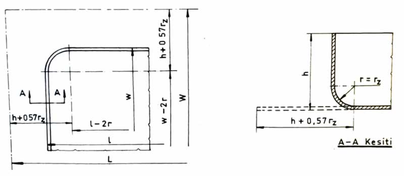
Width of the part to be drawn W = (w — 2r) +2 (h + 0.57.rz)
Length of the part to be drawn L = (l — 2r) + 2 (h + 0.57.rz)
2-) Die corner radius (inner-surface corner radius), (r) > punch nose radius (rz), r > rz
Width of the part to be drawn W = (w—2rz) + 2(h+ 0.57rz)
Length of the part to be drawn L= (l —2rz) + 2(h+ 0.57rz)
Calculating the Drawing Force in Rectangular and Square Drawing
Drawing force P = [ σb . T ( 2π r . C1 + L . C2 ) ]
P = Drawing force, kg
T = Thickness of the sheet material to be drawn, mm
r = Die corner radius, mm
L = Total length of the drawn container’s straight edges, mm
σb = Bending stress of the drawn container material, kg/mm2
C1 = constant coefficient of 0.5. In deep draws [h = (5-6)r], this value rises up to 2.
C2 = constant coefficient of 0.2. Applied in dies with excessive die clearance and no blank holder. In dies with normal clearance and a blank holder, this value is taken as 1.
Draw Depth and Number of Draws
In rectangular and square drawing, the material type, thickness, and the die and punch nose radii affect the number of draws and the draw depth.

Using the two tables above, the drawing die radii and draw-depth ratio are found, and based on this, the number of stages required for the drawing operation is determined.
Importance of Corner Radius
A small corner radius in rectangular drawing dies increases the risk of tearing in the material.
Balanced Material Flow
In square drawing dies, balanced material flow from all four corners is required to obtain a uniform part.
Blank Holder Force
Correctly setting the blank holder force in rectangular/square drawing plays a critical role in preventing wrinkling and tearing.
Related Questions
Cylindrical drawing dies are both cheaper and simpler to design. Also, since this shape has no corners, it greatly reduces the risk of tearing and wrinkling during drawing.
Unlike straight edges, corner areas are critical points where compressive, bending, and drawing stresses all occur simultaneously. This complex stress state is why the corners are the areas most prone to wrinkling or tearing.
Related Posts