

Mechanical Clamping Elements
The forces of mechanical clamping elements are transmitted to the workpieces by means of bolts, hinged arms, clamping cams, and clamping materials.
Advantages of mechanical clamping elements
Large clamping forces. Clamping elements holding themselves in place
Disadvantages of mechanical clamping elements
Very time-consuming clamping
Risk of connection failure from unbalanced clamping forces

Clamping Bolts, Clamping Shoes, and Clamping Supports
In general, workpieces are secured to the machine tool table with T-slot head bolts, clamping nuts, and clamping supports. Clamping force is transmitted to the workpiece and clamping supports through the clamping shoe.

Clamping bolts have roughly 1.5 times the thread diameter due to the high loading they undergo. A hardened washer is placed between the clamping shoe and the clamping nut. Angular deviations between the clamping shoe and the workpiece are compensated for by means of a spherical washer and a wedge seat.

As clamping supports, for example, large stepped supports with a one-sided angled thread, or small stepped clamping supports, are used. Screw-type supports are suitable for stepless height adjustment.
Positioning and support elements are used to position or support workpieces. Heavy workpieces can be adjusted according to the tool’s own position by means of positioning wedges. Support elements are placed under thin-walled workpieces. This ensures the workpieces are machined without bending.
Flat Clamping Parts by Compression
With compression clamping parts, or depth-clamping parts, the workpiece is clamped in a way that doesn’t obstruct the tool’s movement during machining. Thanks to the wedge effect of the flat clamping parts’ clamping supports on the clamping bolt, the workpiece is pressed firmly onto the machine tool table (bed).
Quick-Clamping Assembly
In a quick-clamping assembly, the clamping shoes, clamping bolts, nuts, and clamping supports together form one unit. For this reason, they’re positioned according to the required workpiece heights with hand grips that don’t take up much space. Also, unlike individual clamping elements, these elements cannot be used as versatilely due to their build height.
Toggle-Lever Clamping Fixture, Eccentric and Cam Clamping Fixture
A toggle-lever clamping fixture reaches its maximum clamping force at the dead-center position. In the position past dead center, the toggle arm clamps itself in place. The arrangement of a separate lever in a toggle-lever clamping fixture can vary widely.
In eccentric clamping, the clamping force is obtained via a self-locking eccentric.
A cam clamping fixture, on the other hand, has a clamping cam that acts in the clamping direction.
Toggle-lever, eccentric, and cam clamping elements are generally used together with clamping fixtures. Their characteristics are as follows:
Rapid approach and retraction of the clamping part.
• Self-locking.
• Lower clamping force compared to bolt-and-nut clamping equipment.
Machine Vise
Machine vises are used for clamping individual small parts, and small to medium-sized workpieces in serial manufacturing. The adjustment motion is done with a hand-operated lever in mechanically actuated mechanisms, or with cylinders in pneumatically or hydraulically actuated vises.
Clamping occurs when the clamping jaws come onto the workpiece. At that point, the clamping force is boosted hydraulically or mechanically.
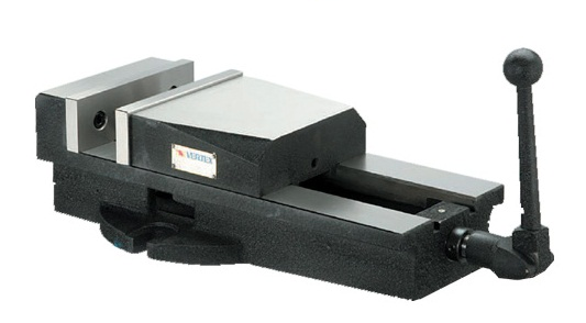
In mechanical clamping, force amplification is achieved via a toggle-lever system. After a pressure spindle’s clamping jaws come onto the workpiece, it drives an extension pin against the toggle lever joint. In this way, the pressure spindle pushes the workpiece forward with an increased clamping force.
Vises for CNC-Controlled Machines
Machine vises for CNC control are manufactured rigidly and have a body that is ground on all sides. Clamping forces can be adapted to the workpiece by a preselection. The repeatability of the workpiece position (the likelihood of each job being clamped in the same position) is very high. Thanks to the ability to change the clamping position and clamping jaws, they can be used versatilely. Vises for CNC-controlled machines can be used as a clamping fixture.
Angular-Motion Clamping Tables
If the surface of a workpiece to be machined needs to make a certain angle with an already-existing surface, angular-motion clamping tables are used. These tables are manufactured either as rigid angle plates, or in a design capable of tilting and rotating.
Round Rotary Tables
Angular indexing motions can be achieved with round rotary tables. With these tables, machining a workpiece from various directions, or manufacturing bolt-circle holes or peripheral holes on cylindrical workpieces, becomes possible.
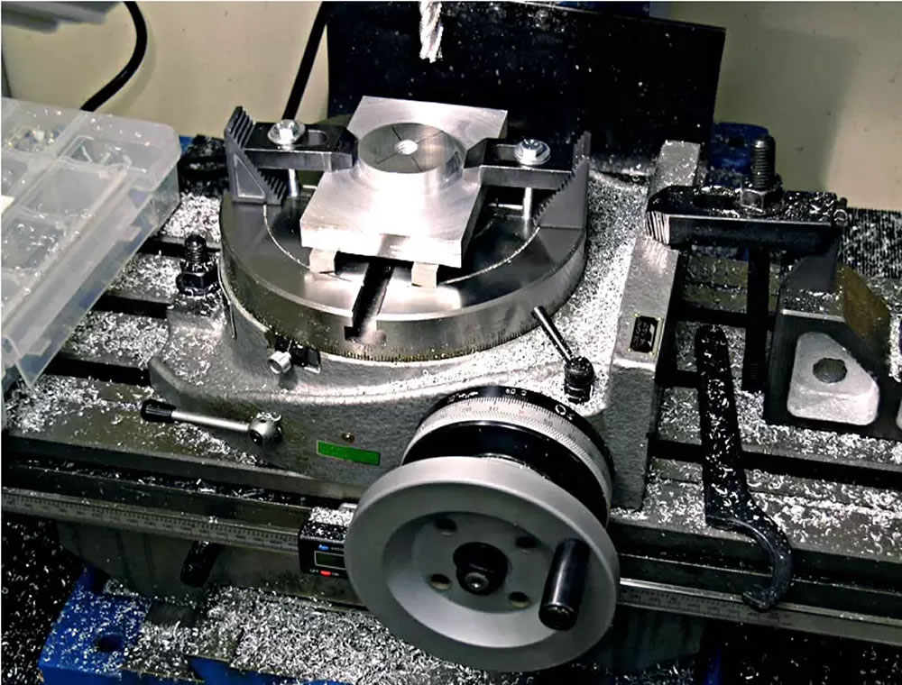
If workpieces need to undergo multi-stage machining such as drilling, deburring, thread cutting, etc., a round rotary table is used for their series production. Angular steps are produced by means of two face gears and two rings that engage each other internally in sequence.
CNC-controlled round tables can have as many angular steps as desired, controllable via the CNC control. These are generally used as the fourth axis of a machine tool.
Magnetic Clamping Fixtures
This clamping method is especially suitable for grinding small, magnetizable workpieces. In clamping plates, the permanent magnet’s circuit can be switched on and off. Clamping plates with electromagnets increase heat loss during operation.
This can lead to the shapes of workpieces changing (deformations). For this reason, to reduce the heat increase and allow the clamping surface to be used better than a simple permanent-magnet type, both magnet types are generally combined together.
After machining is finished, the residual magnetism remaining on the workpieces must be removed. This process is carried out automatically by a control corresponding to the magnetic field, at the moment the circuit is closed.
Related Posts
 Safe Working Rules on a Milling Machine
  G01 Code. Linear Motion with Cutting
  G75 CNC Grooving Cycle Code Explained
  CNC Milling Workshop Operating Instructions
  G02 and G03 Codes: Circular Motion Commands
  CNC Longitudinal Turning Cycle – G90 – G71 – G70
  G00 Rapid Positioning Without Cutting CNC Code
  CNC Lathe G84 Tapping Cycle Explained