
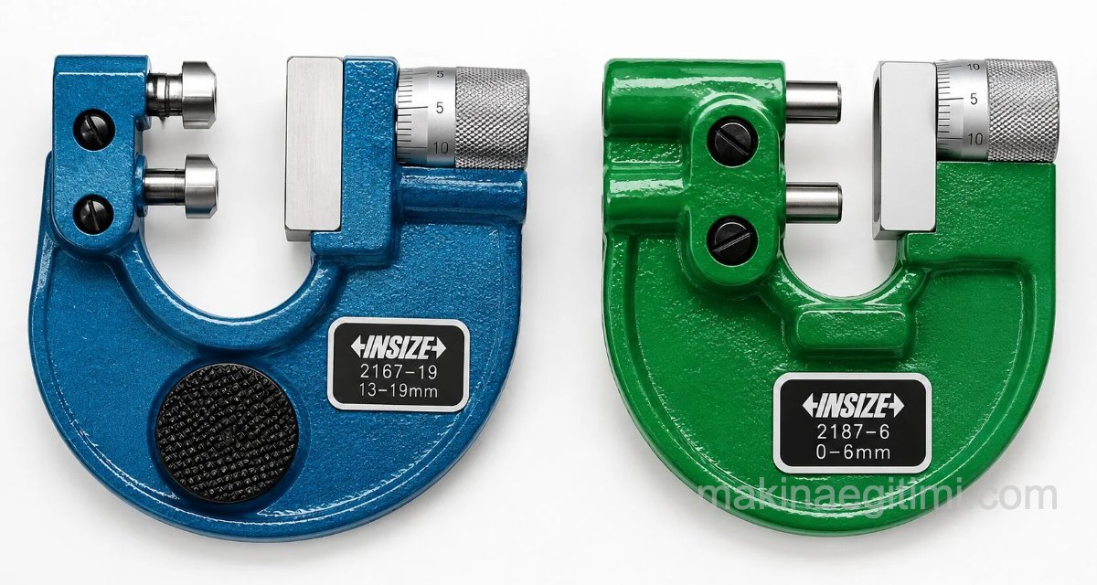
We can classify the types of gauges as follows:
Gauge Blocks (Parallel Gauges)
These are made in the shape of a rectangular prism from high-carbon stainless steel. Their surfaces undergo extremely precise processing. Their measuring surfaces are made so precisely that when combined together to achieve a certain dimension, they adhere to each other strongly. Testing has shown this adhesion force to be around 40 kg/cm².
Johnson gauge sets are prepared as a set of 128 pieces. Measuring and inspection work with Johnson gauges should be done at 20°C. The values marked on the gauges are the gauge’s nominal dimensions.

Properties of Gauge Blocks
- Each gauge block in a set has its own dimensional accuracy, and the desired measurement precision can be achieved at the desired sizes.
- By combining several gauge blocks together, the desired length can be achieved quickly and easily.
- Taking advantage of the surfaces’ flatness, parallelism, and dimensional accuracy, the desired tolerances can be easily achieved.
- The properties of combined gauge blocks remain unaffected as long as there’s no dropping, striking, or similar impact. For this reason, their use in industry is increasing day by day
Gauge series are built starting from the last digit of the dimension. That is, starting from the smallest gauge that makes up the series.
If dimensional accuracy is being achieved by combining two or more gauge blocks, protective wear blocks that stay permanently attached should be fixed to the top and bottom surfaces of the gauge block stack. This way, the other gauge blocks are protected from scratching, impact, and similar effects

Materials of Gauge Blocks
Gauge blocks are generally made from carbon steel and hardenable, wear-resistant chromium-alloy steels. Materials used for gauge blocks need to have the following properties: they must harden well, must not change shape during hardening, must be resistant to wear, must have a very low elongation percentage, and the material must be low-cost and easy to machine.
Gauge blocks are also made from nickel-alloy steels and stainless steels to increase wear resistance. They’re also manufactured from hard metals such as tungsten carbide and chromium carbide. However, gauge blocks made from hard metals are quite costly. Depending on the application, some gauge blocks are also made from copper, quartz, and aluminum alloys
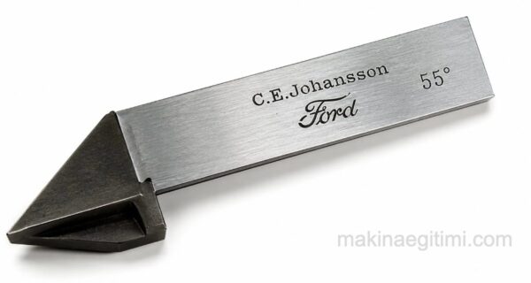
Related Post Johnson Mastarları (Johansson mastarları) ve kullanılışı
Johnson mastarları. Johansson mastarlarının kullanımı. Johansson mastar takımının tanıtımı.Johansson mastarı nasıl kullanılır.
Precision of Gauge Blocks
Gauge blocks are manufactured from steel or ceramic and provide a length reference accurate to the micron level.
Use of Profile Gauges
Profile gauges allow complex geometries to be checked quickly and consistently using a template.
Logic of the Limit Gauge
Limit gauges quickly test whether a dimension falls within the allowed minimum and maximum tolerance limits.
Profile Gauges
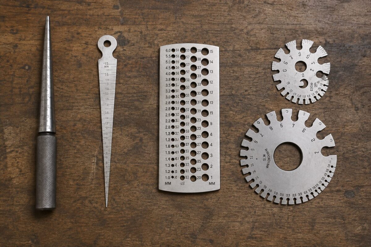
Profile gauges are used for checking parts’ characteristic profiles, cross-sections, wire diameters, cutting edges, and similar features.
Thread-Cutting Tool and Thread Pitch Gauges
They’re used to ensure that thread-cutting tools have the correct profile for the thread being cut, and to check the thread once it’s cut


Limit Gauges
Also known as Go-No Go gauges.
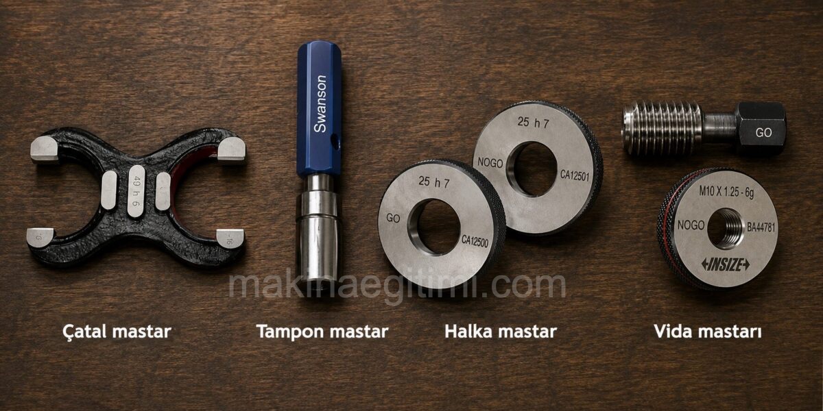
The upper and lower limit dimensions of toleranced parts can be checked with a male gauge for corresponding holes, and with a female gauge for shafts.
The Go gauge checks the largest allowed dimension on shafts and the smallest allowed dimension in holes.
The No-Go gauge checks the largest dimension in holes and the smallest dimension on shafts. A workpiece that fits the No-Go gauge is scrapped
Plug Gauges
(Plug Gauges) Used for checking holes and grooves. The Go side should enter the hole under its own weight. It represents the lower tolerance limit of the hole. Only the tip of the No-Go side should enter. It represents the upper tolerance limit of the hole.

The Go side has a long cylinder, fitted with hard-metal bars to reduce wear. The No-Go side has a short inspection cylinder. This part of the gauge is marked in red, with the upper dimension limit printed on it.

On limit gauges, the part the workpiece can pass through is marked with the word “Go,” green, or no color at all; the part the workpiece cannot pass through is marked with the word “NoGo” or red.

A progressive (stepped) plug gauge where the Go and No-Go parts are designed one after the other on the same piece

A reversible plug gauge, where the Go and No-Go parts are designed either on the same piece or on separate pieces,
and either end can be used
Checking Tolerance With a Go/No-Go Plug Gauge
The video above shows how a plug gauge is used and how tolerance is checked with a Go/No-Go plug gauge.
Snap Gauges
(Snap gauges) Among the types of gauges, snap gauges are used to check the diameter and thickness of workpieces. The Go side has the largest allowed dimension and passes over the part being checked under its own weight. The No-Go side is made slightly shorter, with a small tolerance difference. The No-Go side also has angled inspection surfaces and is marked in red, with the lowest limit value printed on it.
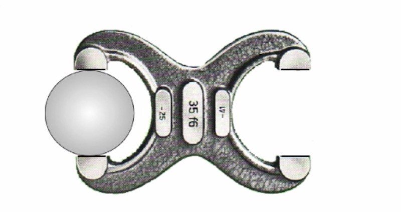
35 f6 Snap gauge, Go position.(above)
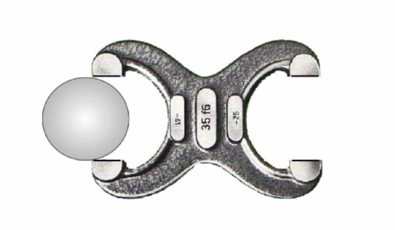
The No-Go position of the snap gauge for the same workpiece. We can say this workpiece was machined within tolerance.
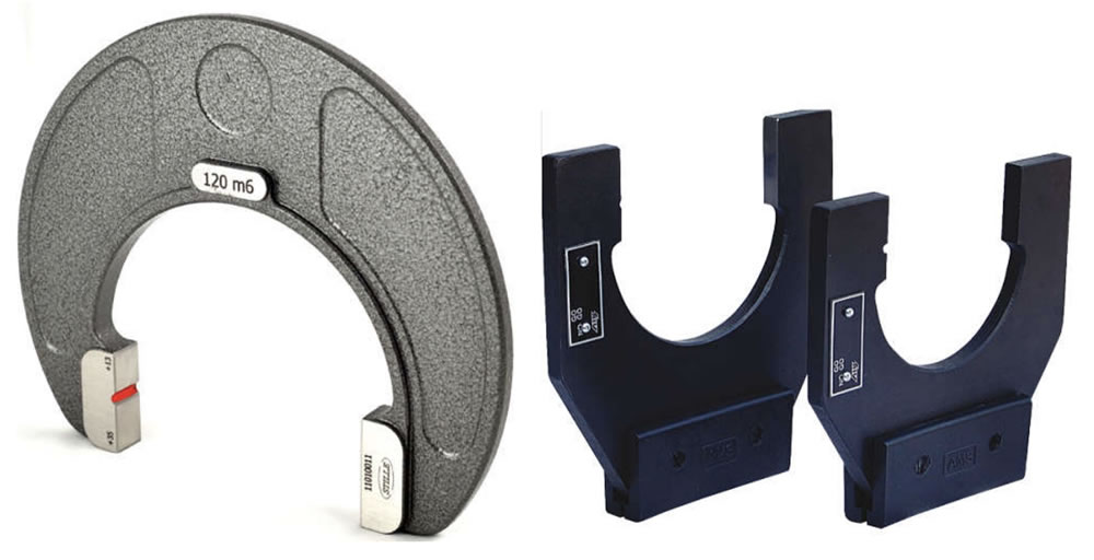
A progressive snap gauge, where the Go and No-Go parts are designed one after the other on the same piece

An adjustable snap gauge where the Go and No-Go parts are designed one after the other on the same piece, adjustable according to the nominal dimension and tolerance value
Checking Tolerance With a Go/No-Go Snap Gauge
The video above shows how a snap gauge is used and how tolerance is checked with a Go/No-Go snap gauge.
Ring Gauges

These gauges are ring-shaped and are used to check the outer diameter of parts with a cylindrical profile (such as shafts, spindles, and parts with cylindrical protrusions). The Go part represents the lower tolerance limit of the cylindrical part
Thread Gauges
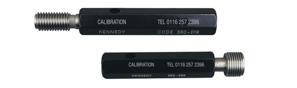
(Thread gauges) These gauges are used for checking threads cut into internal or external cylindrical surfaces. With this check, we can precisely verify whether the major diameter, minor diameter, pitch, and tooth shape of the thread will provide good contact.
Their difference from thread pitch gauges is that they offer more precise and reliable checking.


Related Questions
Parallel gauges (gauge blocks), profile gauges, and limit gauges are the most commonly used types of gauges.
Gauge blocks are manufactured from steel or ceramic and provide a length reference accurate to the micron level.
Limit gauges quickly test whether a dimension falls within the allowed minimum and maximum tolerance limits.
Related Posts
 Mounting Grinding Wheels on the Machine
  What Is a Gauge. Why Is It Used?
  Cutting a Triangular (V) Thread on a Lathe
  Types of Milling Machines
  Information About End Mill Cutters
  Work Instructions at a Drill Press Johnson Gauge Blocks (Johansson Gauge Blocks) and Their Use
  Universal Milling Machine Accessories