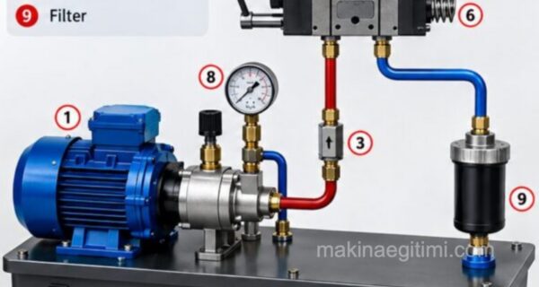
This article’s topic will be hydraulic circuits. Types of hydraulic circuits. Closed hydraulic circuits, open hydraulic circuits. Hydraulic circuit design. Designing open hydraulic circuits. Designing closed hydraulic circuits, and similar topics. Here are the topics:
Open Hydraulic Circuits
In general, if the pump’s suction line is below the fluid level in the tank, and the fluid surface is in direct contact with atmospheric pressure (that is, the surface isn’t sealed), this is called an “open hydraulic circuit,” or in other words, an open-loop circuit.
The pressure balance maintained between the air inside the hydraulic tank and the air in the outside environment gives the pump excellent suction characteristics. Resistance in the supply line must not cause the pressure to drop below the value called the suction lift/suction limit.
Axial piston units are self-priming. However, in certain special cases, the suction side is supplied with low pressure.
In open hydraulic circuits, fluid is delivered to the end user through a directional control valve, and returned to the tank through that same valve.
Where Open Hydraulic Circuits Are Used
Open-loop circuits are the standard circuit used in many industrial and mobile applications. Examples range from machine tool and press drives to cranes and mobile drive systems.
Designing Open Hydraulic Circuits :
Stage 1 – The basic design, consisting of a hydraulic pump and a hydraulic motor/hydraulic cylinder, with a single-direction stroke and output

The basic design, consisting of a hydraulic pump and a hydraulic motor/hydraulic cylinder, with a single-direction stroke and output
1-Tank
2-Fixed-displacement pump
3-Fixed-displacement motor
4-Hydraulic cylinder
5-Suction line
6-Drive speed n= constant
7- Flow rate Q= variable
8- Output speed n= variable
9- Stroke speed v= variable
Stage 2 – Let’s include a directional control valve in the hydraulic circuit:

1-Tank
2-Fixed-displacement pump
3-Fixed-displacement motor
4-Hydraulic cylinder
5-Suction line
6-Drive speed n= constant
7- Flow rate Q= variable
8- Output speed n= variable
9- Stroke speed v= variable
10- Directional control valve for direction selection
Thanks to the directional control valve, the rotation direction/travel direction at the end user can be changed.
Stage 3 – Let’s add a flow control valve and a pressure relief valve to the hydraulic circuit

The components of the open hydraulic circuit above:
1-Tank
2-Fixed-displacement pump
3-Fixed-displacement motor
4-Hydraulic cylinder
5-Suction line
6-Drive speed n= constant
7- Flow rate Q= variable
8- Output speed n= variable
9- Stroke speed v= variable
10- Directional control valve for direction selection
11-Flow control valve for flow adjustment
12-Pressure relief valve
In the open hydraulic circuit above, using a flow control valve (11), the output speed is made variable. The pressure relief valve (12) protects the hydraulic system against overloading.
Stage 4 – Let’s replace the flow control valve with a variable-displacement pump, and add accessories like a filter and cooler to the system
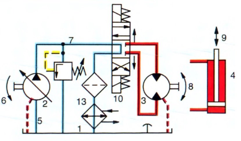
A variable-displacement pump takes the place of the fixed-displacement pump and flow control valve. Other directional control valve functions, like a free-return circuit for the end user, and accessories like a filter and cooler, complete the hydraulic system.
1-Tank
2-Variable-displacement pump
3-Fixed-displacement motor
4-Hydraulic cylinder
5-Suction line
6-Drive speed n= constant
7- Flow rate Q= variable
8- Output speed n= variable
9- Stroke speed v= variable
10- Directional control valve for direction selection
12-Pressure relief valve
13 -Accessories. such as filter, cooler, etc.
Typical Properties of Open Hydraulic Circuits:
- Suction lines: Large diameter, short length
- Directional control valves: Their nominal sizes depend on flow rate.
- Filters/coolers: Their cross-sectional area/size depends on flow rate.
- Tank volume: In liters, several times the maximum pump flow rate
- Pump placement: Next to or below the tank
- Drive speeds: Limited by suction capacity
- Discharge is in the return line, through the valves.
Closed Hydraulic Circuits
Hydraulic systems in which the hydraulic fluid returning from the end user is sent directly back to the hydraulic pump are called closed-loop hydraulic systems. Depending on the pump’s loading direction, there’s a high-pressure side and a low-pressure side.
The pressure on the high-pressure side is limited using pressure relief valves that discharge to the low-pressure side. The fluid stays continuously within the circuit.
Only the leakage losses from the hydraulic pump and motor (depending on operating data) need to be compensated for.
This is (usually) done using a charge pump, typically flange-mounted directly to the main pump. This auxiliary pump continuously draws a sufficient amount of fluid (charge fluid) from a small tank and delivers it, through a check valve, to the low-pressure side of the closed-loop circuit.
The portion of the fluid supplied by this charge pump, which runs in an open circuit, that isn’t needed is sent to the tank through a pressure relief valve. Because the low-pressure side is continuously replenished, this pump can achieve high operating characteristics.
Designing Closed Hydraulic Circuits :
Basic Design

Basic design with a variable-displacement pump and motor. The pump rotates in only one direction, while the motor can rotate in both directions. The pump’s swashplate angle can be adjusted steplessly on either side of the zero position — meaning the flow direction and flow rate can be changed. The motor’s swashplate can also be tilted in one direction and adjusted steplessly as well
1- Hydraulic pump
2- Hydraulic motor
3- Flow rate Q = Variable
Adding Pressure Relief Valves

1- Hydraulic pump
2- Hydraulic motor 3- Flow rate Q = Variable
4 – Pressure relief valve against overloading
Pressure relief valves are used to achieve the desired maximum pressure values. A separate pressure relief valve is fitted for each pressure side.
Compensating for Leakage Fluid

In hydraulic circuit design, the leakage flow from the pump and motor is directed to a small tank and needs to be compensated for.
1- Hydraulic pump 2- Hydraulic motor 3- Flow rate Q = Variable
4 – Pressure relief valve against overloading 5-Leakage oil line 6- Tank for leakage oil
Preventing Cavitation, Adding a Filter and Cooler
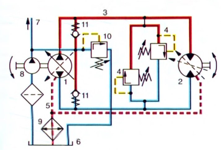
The hydraulic system is completed by adding a charge pump to make up for leakage and control the pump, check valves to prevent cavitation, pressure relief valves for the charge and main circuits, and accessories like a filter and cooler. 1- Hydraulic pump
2- Hydraulic motor
3- Flow rate Q = Variable
4 – Pressure relief valve against overloading
5-Leakage oil line 6- Tank for leakage oil
7- Line for pump control
8 -Charge pump for anti-cavitation
9 – Filter, cooler, etc.
10- Charge pressure relief valve
11 -Check valve
Semi-Closed Hydraulic Circuits
Semi-closed-loop circuits are a mix of both types of control circuit, and are used in applications requiring volumes to be balanced, for example with the help of anti-cavitation check valves (for example, when using a single-rod cylinder).
Related Posts