

In this article, we’ll cover the OFFSET command among AutoCAD commands. We’ll see what the offset command is and how the OFFSET command is used. We’ll reinforce how the offset command is used with a sample part drawing. Then we’ll give you drawing examples for offset command practice.
We could call the offset command “parallel copying” as its plain-language description. It’s the command that copies a line or object parallel to itself, at a distance we specify.


How Is the OFFSET Command Used
O + ENTER
TYPE THE DISTANCE + ENTER
SELECT THE OBJECT + ENTER
SELECT THE SIDE
If we want to use this offset command repeatedly, from that point on we simply continue with just
SELECT THE OBJECT
SELECT THE SIDE
and repeat this cycle.
We can keep offsetting until we exit the command with Esc.
The Difference Between the OFFSET Command and the COPY Command
We said the offset command performs a parallel copy. To grasp what that means and how it differs from copying with COPY, let’s show the difference between the two commands with an example.

We’ll apply COPY to one of the two rectangles we drew on screen, and OFFSET to the other. Let’s see what happens.

As you can see, the rectangle we applied COPY to and the rectangle we applied OFFSET to produced different shapes. The OFFSET command gave the rectangle a wall thickness and created a frame.
You can watch this in the video below.
Now, if you’d like, let’s share a detailed video walkthrough about the offset command
Video: How Is the AutoCAD OFFSET Command Used
How to use AutoCAD’s offset command, presented by Gökçegün from yakinkampus.com.
Sample AutoCAD OFFSET Command Application
When drawing in AutoCAD, you first need to decide on a drawing strategy. Which commands will get me through this drawing the fastest? In what order should I do it? Where should I start the drawing? You should be able to ask yourself questions like these and get an instant answer. To do that, you need to spend a good amount of time with the program and practice with a variety of drawings.
After a while, as soon as you see the part you need to draw, how you’ll draw it and which commands you’ll use at which stages will come to mind on their own.
OFFSET is one of the commands you can use in many drawings. You’ll notice that people working as professional drafters in the industry use this command very effectively. Now let’s look at a sample application of what we can do with this command.

Let’s see how we can draw the simple stepped shaft shown above using the OFFSET command:
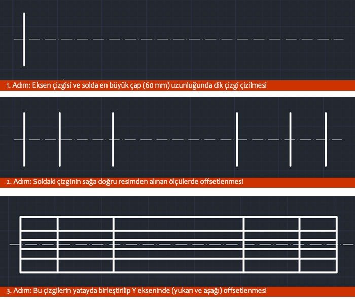
We started the drawing by first drawing a vertical line. This line’s length equals the largest diameter dimension (60 mm).

In step 2, we proceeded by offsetting along the x-axis by the step dimensions taken from the drawing. Then we connected the base and top points of these lines and offset them upward and downward as well.
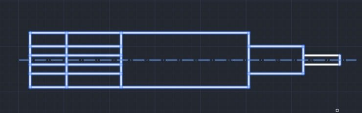
Then, using the TRIM command, we trimmed away the parts we didn’t want, so as to reveal our stepped shaft.
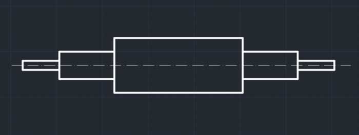
Once we finished trimming, our part’s outline emerged. From here on, it’s just dimensioning.
So is there an easier way? Let’s take a look at that too…
Experienced AutoCAD users, as soon as they look at the drawing, notice that the shape is symmetric about the centerline and realize a MIRROR reflection could be used.
Method 2 (A More Practical Approach)
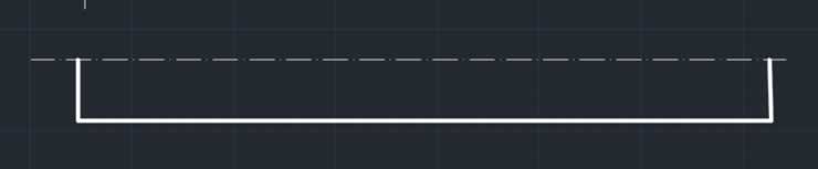
In addition to the centerline, let’s start with a line 30 mm high (half of the largest diameter) and another line 340 mm long.

Let’s offset the vertical line by the step lengths of the stepped shaft.

Let’s also offset the horizontal line by the differences between the radii. That is, as given in the dimensions above.

Let’s trim with the TRIM command to form the steps of our stepped shaft.

Once the trimming is done, all that’s left is to mirror it upward from the centerline using MIRROR.
OFFSET Command Example Drawings
We mentioned that you need to do a lot of practice drawings to be able to work effectively with AutoCAD’s OFFSET command. Below are example drawings that can help with your practice and that make use of the offset command.


Related Posts
 AutoCAD Example Drawings 2 – Complex Drawings
  2D Dimensioned Drawing Examples – Part 1
  2D Sketch Drawing Examples – Part 5
  How to Add Tolerance in AutoCAD. Adding Tolerance
  AutoCAD Drawing Exercise 3 – MIRROR Command
  2D Sketch Drawing Examples – Part 3
  Introduction to Computer-Aided Drawing – Exercise Drawings
  A Few Tricks for Productivity With AutoCAD