

This article is the 4th post in our “How to Build a Robot” series for beginners.
A robot with its hardware assembled and software loaded rarely behaves as expected on its first run. In this final part of the series, we look at how to systematically test a completed robot project, how to calibrate its sensors, and how to move the robot toward a basic level of autonomy.
A Gradual Testing Approach: From Subsystem to Whole
Running a newly completed robot directly in full autonomous mode makes it hard to pinpoint the source of any problem that arises. Instead, a gradual testing approach is recommended. In the first stage, each motor is tested individually to verify it spins in the correct direction and at the expected speed.
In the second stage, each sensor is tested on its own; for example, checking whether the distance values an ultrasonic sensor prints to the serial monitor match actual measurements. In the third stage, sensor and motor integration is tested in a simple scenario — for example, expecting the motor to stop when the sensor reads a value below a certain distance. Only after these three stages are successfully completed should you move on to testing the robot in its full mission scenario.
Sensor Calibration
A sensor’s out-of-the-box factory values may not give directly reliable results under the conditions of the actual environment being used (floor color, light level, surface roughness). For this reason, sensor calibration should be performed in the real environment where the robot will operate.
For example, for the IR sensors used on a line-following robot, the raw values given while over the floor and while over the line are measured separately, and a threshold is set between these two values.
For ultrasonic sensors, keep in mind that different surface materials (soft fabric, hard metal) reflect sound waves differently, and calibration should be done with the surfaces the robot will actually encounter. For IMU modules, it’s common practice to run a brief zeroing routine (offset calibration) lasting a few seconds at startup, to reduce drift caused by temperature changes.
Debugging Methods
Debugging robot software presents different challenges than desktop software development, because the source of an error can be hardware, software, or an interaction between the two. Printing live sensor values and decision-making state over the serial port (serial debugging) is one of the most basic and effective debugging methods.
For visual feedback, LEDs mounted on the robot that light up in different colors for different states (for example, red when an obstacle is detected, green during normal movement) make it easier to visually track the robot’s internal state. In more complex projects, logging sensor data and motor commands over time and plotting them on a computer (data logging and visualization) is useful for detecting recurring or intermittent issues.
Common Testing-Stage Problems
One frequently encountered problem in robot testing is loose connections on a breadboard breaking due to vibration while the robot moves; this can cause the robot to exhibit erratic behavior and is usually resolved by soldering the final circuit or securing it with connectors.
Another common issue is that motors don’t spin as powerfully as they did initially, because voltage drops as the battery’s runtime progresses; this means calibration values need to be tested not just with a fully charged battery, but at different charge levels as well.
Additionally, since changes in ambient light (day-night, fluorescent light flicker) can affect the consistency of optical sensors, it’s recommended to repeat tests under the lighting conditions the robot will actually be used in.
Moving to a Basic Level of Autonomy
Once testing and calibration are complete, the robot can be moved to a basic level of autonomy. At this stage, the robot becomes able to respond to changes in its surroundings without human intervention, based on predefined rules. For example, a robot with an obstacle-avoidance behavior added can stop and change direction when it detects an object in its path.
The level of autonomy can be increased gradually: simple if-else-based reactive behaviors are sufficient at first, while later stages can involve combining data from multiple sensors (sensor fusion) and more complex decision trees or state machines.
For mechatronics students, the natural next step after this point is moving from simple reactive behaviors to more advanced autonomous navigation techniques such as path planning and mapping (SLAM).
Documentation and Reproducibility
The final step of a completed robot project is documenting all the design decisions made, the circuit schematic, the code structure, and the calibration values.
This documentation both makes future development of the project easier and allows the same platform to be reproduced by another student or team in a repeatable way. Using simple drawing tools for circuit schematics and version control systems (such as Git) for code is an increasingly common engineering practice in mechatronics projects.
Conclusion
The testing, calibration, and transition-to-autonomy stage is the final phase where a robot project turns from a plan on the desk into a system that reliably works in the real world. A gradual testing approach, systematic sensor calibration, and structured debugging methods make it possible to quickly identify and resolve the problems that come up.
The planning, hardware, software, and testing steps covered across this four-part series provide a foundational framework for mechatronics students and anyone curious about robotics to bring their own robot projects to life in a systematic way.
See the link below for the “intermediate level” robot-building information series:

Related Post Robot Kinematics and Dynamics: Foundations of Mathematical Modeling
Forward and inverse kinematics, the Jacobian matrix, Newton-Euler and Lagrange dynamics, and holonomic vs nonholonomic mobile robot constraints.
Frequently Asked Questions
The robot should be tested with a gradual approach — first testing the motors and sensors individually, then verifying integration with simple scenarios — rather than jumping straight into the full mission scenario.
Because a sensor’s out-of-the-box factory values can vary depending on the conditions of the environment it’s used in, measurements need to be taken in the environment the robot will actually operate in to determine the correct threshold values.
Printing live data over the serial port, using status-indicator LEDs, and logging and visualizing sensor/motor data are commonly used debugging methods in robot software.
Once testing and calibration are complete, a basic level of autonomy can be reached by adding simple reactive behaviors based on predefined rules (such as obstacle avoidance) to the robot.
Documenting the circuit schematic, code structure, and calibration values makes it easier to develop the project further in the future and to have it reproduced by someone else in a repeatable way.
Related Posts
Robot Kinematics and Dynamics: Foundations of Mathematical Modeling  2026 Developments in Robotics Technology: The Age of Physical AI
 Robot Software Architecture with R.O.S. (Robot Operating System)
 How to Build a Robot? Part 3: Software and Control Algorithms
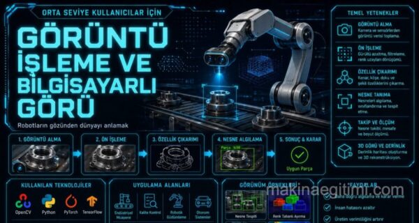 Robot Perception Through Image Processing and Computer Vision
 Industrial Robot Applications: Sector Use Cases and Technical Features
 Robotic Technology in Türkiye: Domestic Ventures and Projects
 Robot Films Worth Watching: The Best Recent Robot-Themed Movies