
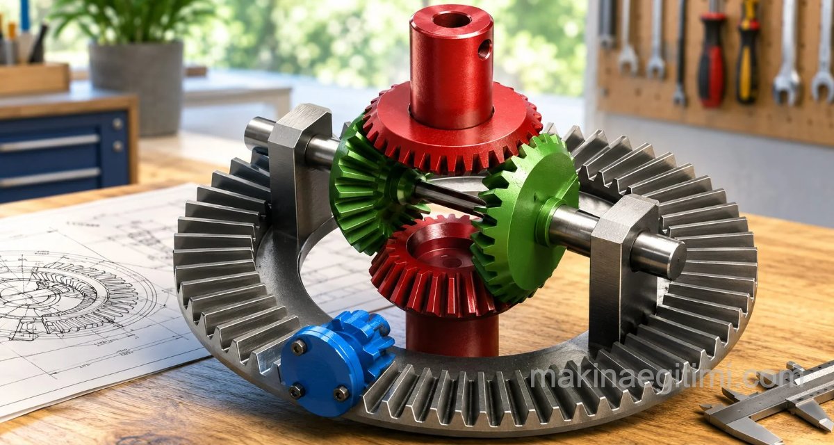
Before we get to the differential gear assembly and detail drawings, let’s touch on what a differential system is. The differential system is a gear system in vehicles that transmits the rotational motion it receives from the gearbox to the wheels, allows the wheels on the inside and outside of a turn to rotate at different speeds while cornering, and, while transmitting motion to the wheels, increases the torque coming from the transmission while reducing the rotation speed.
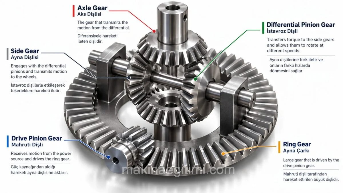
Inside the differential system are gears such as the crown pinion gear, ring gear, spider gears, and axle (side) gears.
The differential’s location in the car. The axle gears are connected to the front wheels, while the pinion gear is connected to the rear wheels by way of the driveshaft coupling.
SolidWorks Assembly and Part Solid Models of Differential Gears
From the links below, you can download 3D SolidWorks drawings of automobile differential gears. The SLDASM file is the assembly file, which you can open in the SolidWorks program. The SLDPRT files are the part drawings. You can also open these files with the SolidWorks program.
Download differential_gear_asm.SLDASM
Download differential_gear_asm.IGS
Download differential_gear_asm.STEP

ring gear Download RINGGEAR1-1.sldprt

crown pinion gear
(pinion gear SolidWorks drawing)
Download PINNIONGEAR-1.sldprt

spider gear
(SolidWorks bevel gear drawing)
Download BEVELGEAR_1-1.sldprt

Spider gear, one of the differential’s parts
(Bevel gear SolidWorks drawing)
Download BEVELGEAR-1.sldprt

axle gear
(Bevel gear SolidWorks drawing Download BEVELGFORRING-1.sldprt
Related Posts
 AutoCAD Drawing Exercise 2 – ARRAY Command
  How to Add Tolerance in AutoCAD. Adding Tolerance
  Isometric Drawing and View Examples
  2D Sketch Drawing Examples – Part 3
  AutoCAD Drawings of Machine Parts
  2D Sketch Drawing Examples – Part 5
  A Few Tricks for Productivity With AutoCAD
  Introduction to Computer-Aided Drawing – Exercise Drawings