

In this article, part of our machine technology CNC lessons section, we’re covering two preparatory function codes: G02 and G03. We’ll look at what the G02 code does, what the G03 code is, and where they’re used. We’ll also go over sample usage of the G02 and G03 CNC codes.
Clockwise Motion
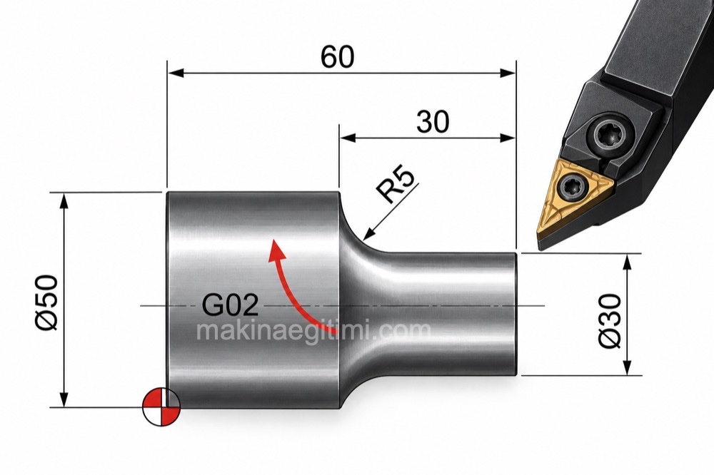
The G02 code makes the tool follow a clockwise circular path on the CNC machine.
Counterclockwise Motion
The G03 code is the command that makes the tool move in a counterclockwise circular path.
Defining the Radius
In circular motion commands, the arc’s radius is typically specified either with the R parameter or with I, J, K center coordinates.
The G02 Code
This is the clockwise circular motion command. It’s used to produce concave (internal) radii. Circular movements to the target point are made at feed rate F, either by specifying the desired radius value or by defining the radius center.
How Is the G02 Code Used?
Method 1: Defining the radius of the circular motion
G02 X….. Y….. R….. F…..
X,Y = coordinates of target point B
R = radius of the circular motion
F = feed rate
Method 2: Defining the center of the circular motion
G02 X….. Y….. I….. J….. F…..
X,Y = coordinates of target point B
I = distance of the radius center from the starting point of the circular motion, along the X direction
J = distance of the radius center from the starting point of the circular motion, along the Y direction
F = feed rate

The G03 Code
This is the counterclockwise circular motion command. It’s used to create convex (external) radii. Circular movements to the target point are made at feed rate F, either by specifying the desired radius value or by defining the radius center.
How Is the G03 Code Used?
Method 1: Defining the radius of the circular motion
G03 X….. Y….. R….. F…..
X,Y = coordinates of target point B, R = radius of the circular motion
F = feed rate

Method 2: Defining the center of the circular motion
G03 X….. Y….. I….. J….. F…..
X,Y = coordinates of target point B
I = distance of the radius center from the starting point of the circular motion, along the X direction
J = distance of the radius center from the starting point of the circular motion, along the Y direction
F = feed rate

G02 and G03 Commands, CNC Program Examples
G50 S2000 T0300
G96 S200 M03
G00 X0 Z3.0 T0303 M08:
G42 G01 Z00 F0.2
G03 X20.0 Z-10.0 R10.0:
G01 Z-50.0:
G02 X100.0 Z-74.385 R45.0
G01 Z-125.0:
G40 U2.0 W1.0
G00 X200.0 Z200.0 M09 T0300
M30

G02 and G03 CNC Program Example 2:
G50 S2000 T0300:
G96 S200 M03:
G00 X35.0 Z5.0 T0303 M08:
G01 Z-20.0 F0.2:
G02 X67.0 Z-36.0 R16.0
G01 X68.0:
G03 X100.0 Z-52.0 R16.0:
G01 Z-82.0:
G00 X200.0 Z200.0 M09 T0300:
M30: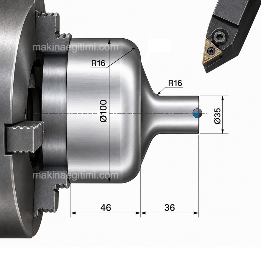
For a page that briefly introduces CNC G and M codes, see: > List of CNC G Codes and Their Meanings
Related Questions
G02 makes the tool move in a clockwise circular path, while G03 does the opposite, producing counterclockwise motion. Which direction an arc or circle is cut in depends on which of these two codes is used.
The R parameter only gives the arc’s radius, while I and J values define the exact coordinates of the arc’s center point. This gives a more precise definition, especially when cutting a full circle or in cases where defining by radius alone could be ambiguous.
Related Posts
 CNC G Code List and Meanings (Beginner’s Guide)
 CNC Milling Workshop Operating Instructions
 CNC Longitudinal Turning Cycle – G90 – G71 – G70
 The Structure of CNC Milling Machines
 Mechanical Clamping Elements on Machine Tools
 The World’s Most Modern CNC Machines Video Series
 G74 CNC Peck Drilling Cycle Explained
 What the Keys on the CNC Milling Control Panel Mean