
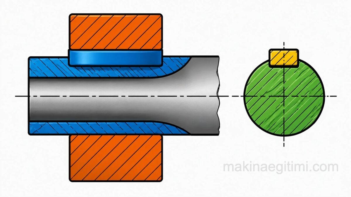
Keys are machine elements used to removably join machine parts such as gears, pulleys, and couplings to shafts.They act as the medium that transfers rotary motion from the shaft to the machine part mounted on it.
Keys are made in various shapes and with various properties depending on where they will be used. We can list the types of keys as follows:
| TRANSVERSE (CROSS) KEYS | LONGITUDINAL (PARALLEL) KEYS |
|---|---|
| Single-taper transverse keys | Tapered (drive-fit) keys |
| Double-taper transverse keys | a) Plain (flat) key b) Gib-head key c) Tangent key d) Woodruff key |
| Untapered (parallel/sliding-fit) keys | |
| a) Woodruff keys | |
| b)Tangent keys | |
| c)Splined shafts |
TRANSVERSE (CROSS) KEYS
These are keys fitted perpendicular to the shaft axis. Rather than joining parts together, these keys are mainly used to resist transverse loads and for adjustment purposes. They are also used where parts need to be removed and refitted frequently.
For this type of key, plain carbon steels with a tensile strength of 60 N/mm² are used.
In transverse keys, the taper of the key varies depending on the working conditions.
Where the connection doesn’t need to be dismantled often (for adjustment purposes): 1:5 to 1:10
Where it is meant to come loose on its own, it’s made 1:15 to 1:25.
For tight (rigid) joints, 1:30 to 1:40
In transverse keys, the key thickness is between 1:3 and 1:4 of the shaft diameter.
Role of the Transverse Key
Transverse keys are used to secure two parts together by clamping them perpendicular to the shaft axis.
Role of the Longitudinal Key
Longitudinal keys transmit torque by preventing parts such as gears and pulleys from rotating on the shaft.
Standard Key Dimensions
Key width and height are specified in tabular form in the DIN standards according to the shaft diameter being carried.
LONGITUDINAL (PARALLEL) KEYS
Longitudinal keys are keys that run parallel to the shaft axis. There are two kinds: tapered (drive-fit) keys and untapered (parallel/sliding-fit) keys.
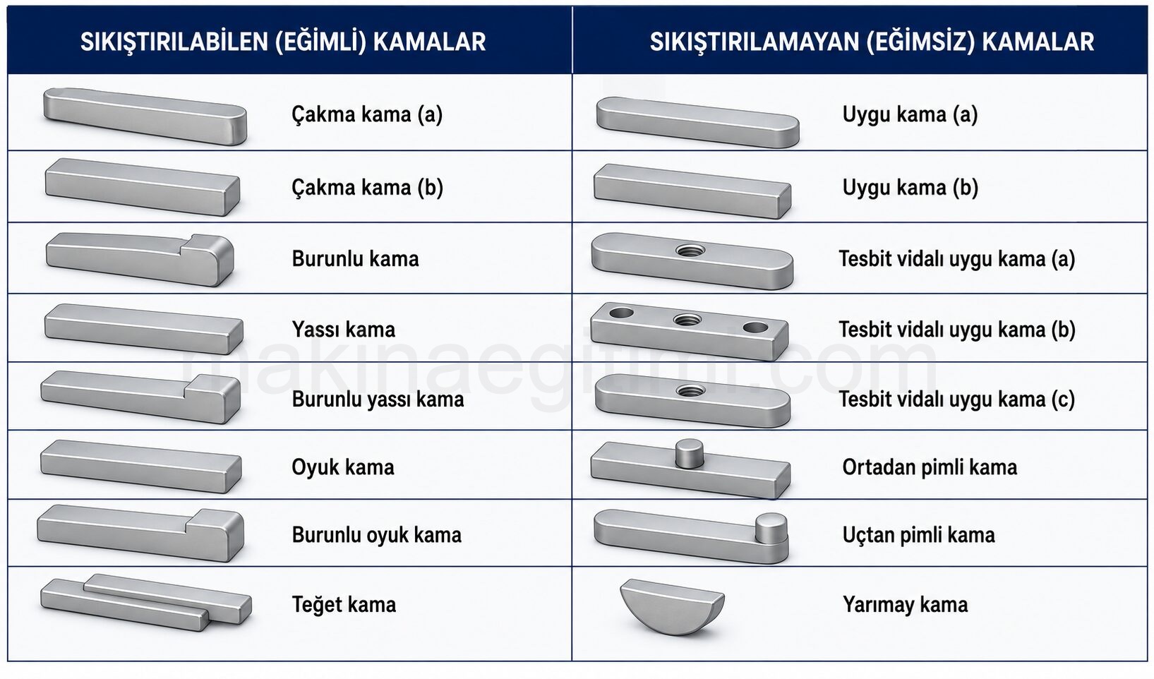
In tapered keys, a taper of 1:100 is given to the top surface of the key and the groove cut in the hub. This taper creates the clamping action by wedging the shaft and hub apart.
Longitudinal keys are generally made from plain carbon steel (grade ç1060), or, on request, from heat-treated (quenched-and-tempered) steel or case-hardening steel. They are sold on the market under the name “key steel.”
Key steels up to 25 mm have a tensile strength of 50 N/mm², while those above 25 mm have a tensile strength of 60 N/mm². Key steels are manufactured straight, bright-finished, and to precise dimensions, in square, rectangular, and flat rectangular cross-sections
How Longitudinal Keys Are Designated per the Turkish Standard (TSE)
When ordering longitudinal keys, the key name, dimensions, and TS number are specified. For example, the designation for a gib-head key with width b = 16, height h = 10, and length l = 180 mm is: Gib-head key 16x10x180 TS147/6
Tapered (Drive-Fit) Keys
In tapered keys, a taper of 1:100 is given to the top surface of the key and the groove cut in the hub. This taper creates the clamping action by wedging the shaft and hub apart.

Tapered plain thick key and its assembly (Type A)

Tapered plain thick key (Type B) and its assembly
Untapered Keys (Parallel/Sliding-Fit Keys)
Parallel/sliding-fit keys serve to transmit and resist forces applied to their side faces. They function as fitting or sliding keys. There is a gap between the top surface of the key and the hub. It is fitted tightly into the shaft keyway.

Woodruff Key
Shaped like a half-moon, it is fitted into a matching half-moon-shaped groove cut in the shaft. Keyways for these are cut with special (T) milling cutters. This is a type of key widely used in machine construction, machine tools, and pump shafts. They are made from steels with a tensile strength of 50 kg/mm².

Shaft, Pulley, Nut, Washer, Woodruff Key — unassembled technical drawing
AutoCAD DWG // PDF

Shaft, Pulley, Nut, Washer, Woodruff Key — assembled drawing
AutoCAD DWG // PDF
Tangent Keys
Used for transmitting large forces. Used for shaft-and-hub connections with diameters greater than 60 mm, in places with very large torques, impact loads, and similar conditions.
Tangent keys have a taper of 1:100, and during assembly, a pair of tangent keys offset by 120° is used. If a difficulty is encountered, the offset between the keys can be taken as 180°.
Splined Shafts 147/14-18
Used for transmitting large torques and large amounts of power, in motor vehicles, in heavily loaded gearboxes, and similar applications. They work by allowing movement along the shaft axis.

For detailed information, see:
What Is a Splined Shaft? Where Is It Used
How Is a Splined Shaft Made?
Related Questions
Since these keys are positioned perpendicular to the shaft axis, they offer practicality for connections that need to be dismantled and refitted often or that require fine adjustment, rather than continuous power transmission. This makes them suitable for temporary or adjustable joints rather than permanent ones.
In a connection that isn’t meant to be dismantled often, a smaller taper makes it harder for the key to loosen on its own. In places where easy removal is desired, a larger taper is preferred so the key can be pulled out easily.
Related Posts
 Standard Representation and Dimensions of a Washer
 Various Bolt Drawing Examples, Technical Drawings
 Types of Cotter Pins and Dimensional Standards
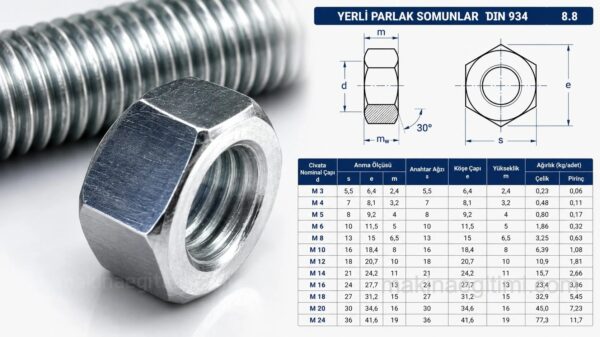 Nut Drawing and Dimension Tables
 Formulas for Gear Drawing and Manufacturing
 Dowel Pin Drawings – AutoCAD DWG and PDF
 Dowel Pins – Types and Standards of Dowel Pins
 AutoCAD Drawings of Machine Parts