
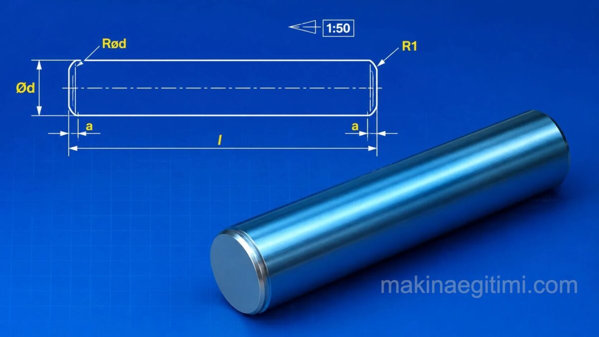
What Is a Dowel Pin
Dowel pins are cylindrical machine elements used to fix the relative position of mating parts, holding them in place, or to center them.
Where Are Dowel Pins Used

In the technical drawings above, on the left, the relative position of two parts is being fixed, while on the right, a grooved dowel pin performs a centering function. Dowel pins are shown as if not sectioned, and are not hatched, in sectional drawings.
Cylindrical Dowel Pins
Cylindrical dowel pins are used to center and position parts with a precise interference fit.
Taper Dowel Pins
Taper dowel pins are made with a slight taper angle, providing a tight, self-locking connection.
Spring (Elastic) Dowel Pins
Thanks to their slotted cylindrical structure, spring pins can flex to compensate for small variations in hole tolerance.
Types of Dowel Pins
Dowel pins are standardized in TS 2337. According to this standard, dowel pins are generally divided into 4 categories.
Cylindrical Dowel Pins
The technical drawing below shows the standard designation and dimensions of cylindrical dowel pins, whose standard shape and dimensions are given in TS 2337/1.

Designation of a cylindrical dowel pin with a nominal diameter d = 10 mm, nominal length l = 30mm, made from unhardened steel, with a tolerance class of m6:
Cylindrical dowel pin TS 2337/1 EN ISO 2338- 10m6x30-A-Fe

Taper Dowel Pins
Taper dowel pins, whose standard shape and dimensions are given in TS 2337/12, are made with a taper of 1:50. The technical drawing below shows a taper dowel pin along with its symbolic designation.

Designation of a taper dowel pin with d=10mm, l=30mm:
Taper dowel pin TS 2337-5 EN ISO 22339-A-10×30-Fe

Threaded Taper Dowel Pins

Dimensions and symbolic designation of threaded taper dowel pins, whose standard shape and dimensions are given in TS 2337
Designation: Pin 5×50 TS 2337/13 9S Mn Pb 28
Grooved Dowel Pins
These are generally used for centering. They’re made in cylindrical and taper forms, and have three grooves around their circumference. The figure below gives the drawing and dimensions of two grooved dowel pins.

Example Technical Drawing of a Dowel-Pinned Joint

Download the AutoCAD drawing of threaded dowel-pinned joints
Press-Fit Bushings
A press-fit bushing (split bushing) is a bushing-shaped machine element with a slot running its full length, which always stays tight and never loosens wherever it’s used. Since they’re made of spring steel, they exert outward pressure wherever they’re fitted, holding tight.

The technical drawing above shows a press-fit bushing and how it’s used to secure a gear onto a shaft.
Related Questions
A taper pin’s slightly angled shape means it grips progressively tighter as it’s driven into the hole. This increasing grip makes it harder for the pin to loosen on its own, creating a more secure joint.
These pins have a slotted, flexible structure and can compress slightly as they enter the hole, then spring back out like a spring. This flexibility compensates for small variations in hole diameter while still keeping the pin seated tightly.
Related Posts
 Various Bolt Drawing Examples, Technical Drawings
 AutoCAD Example Drawings 2 – Complex Drawings
 Types of Cotter Pins and Dimensional Standards
 Formulas for Gear Drawing and Manufacturing
 Spur, Helical, and Bevel Gear Cutting Exercises
 Washer Die Assembly and Detail Drawings – Dwg pdf
 Vise Technical Drawing – Assembly and Detail Manufacturing Drawing
 Compression Spring. Compression Spring Calculation and Drawing