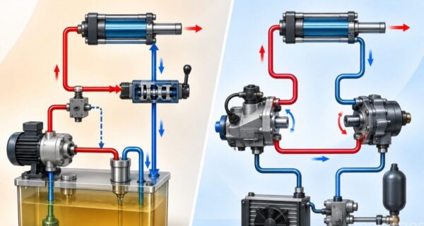
In this article, as an example of hydraulic system applications, we’ll look at a hydraulic system that sets the feed speed on a lathe. We’ll identify the hydraulic circuit components belonging to this example system and build the hydraulic circuit diagram.
Hydraulic Application: Feed Speed Adjustment on a Lathe


On a lathe, the feed motion that has until now been done by hand is to be carried out hydraulically instead. It’s required that the feed motion be adjustable and that it not be affected by variations in the forces acting on the tool.
In the first circuit diagram for this task, a flow control valve is placed in the supply line. With no load applied, the speed value is set to v = 0.3 m/s. It’s observed that as the forces acting on the tool increase during machining, the feed speed decreases. Based on this circuit diagram, the following values were measured.
Circuit diagram under no-load operation (above)
Circuit diagram under the effect of external forces (above)
Comparing the values obtained from both circuit diagrams, the following results were obtained:
Under loading, the pressure value at the pressure relief valve p₁ rises from 48 bar to 49 bar. This pressure rise causes the pressure relief valve to send more fluid back to the tank.
The pressure difference at the flow control point Δp drops from 43 bar to 19 bar. This drop in pressure difference indicates that the flow rate has decreased.
If load variation is present, a simple flow control valve is not suitable for achieving constant-speed feed motion.
For this reason, a pressure-compensated flow control valve is used in such situations.
A pressure-compensated flow control valve consists of two flow control units. One of these, which we could call the adjustable restrictor, allows the desired flow rate to be set.
The other, which we could call the pressure balance or automatic compensator, makes the necessary adjustment based on the valve’s inlet and outlet pressures to keep the desired flow rate constant, even in the event of load variation. Under no-load conditions, the combined resistance of both units, together with the pressure relief valve, affects how the flow is divided. When a load is applied, the automatic compensator reduces the resistance in the valve in proportion to the effective load. As a result, the pressure difference between the inlet and outlet of the adjustable restrictor remains constant.
If the 2-way flow control valve is connected into the circuit in reverse, it acts either as a flow control valve (in which case the automatic compensator is fully open) or as a check valve (in which case the automatic compensator is fully closed).
Related Posts