

Dear readers, today we are going to tell you how a small cylinder joining two pieces of metal became the symbol of an age, and how that age came to an end. The subject is the rivet. From the end of the nineteenth century to the middle of the twentieth, almost every large metal structure — from ships to bridges, from the Eiffel Tower to aircraft — had rivets in its backbone. Then one day this hundred-year reign ended, not suddenly, but irreversibly. Inside this story there is an “unsinkable ship” that sank, warships that broke in two, and a mysterious puzzle solved by a woman engineer.
How Did the Age of the Rivet Begin?
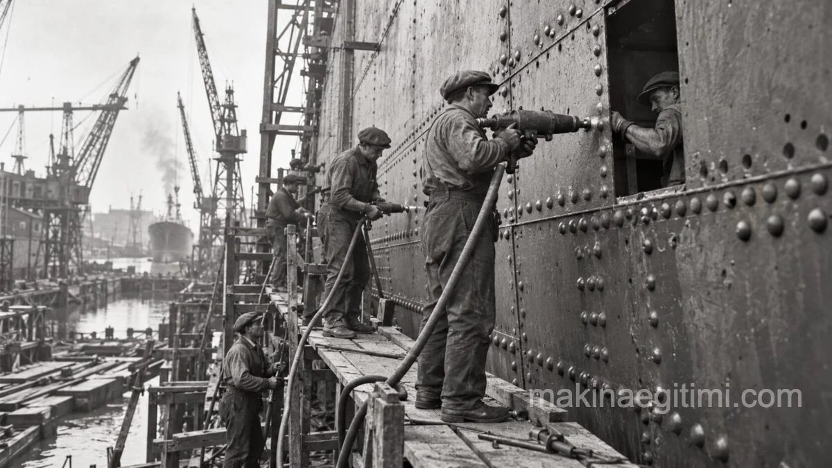
The idea of the rivet is in fact very old; archaeologists have found riveted metal artefacts going back as far as the Bronze Age. The true golden age of the rivet, however, arrives with the industrial revolution. Cheaper iron and steel production, the spread of steam engines and the start of construction of great bridges and enormous ships turned the rivet into the fundamental joining technology of an era.
Riveting was an almost choreographic job that required a team of four. One person heated the rivet until it glowed, a second placed the red-hot rivet in the hole, a third held the rivet steady from the other side with a holding-up tool, and a fourth formed a second head by hammering the other end of the rivet with a heavy hammer or a pneumatic gun. As the rivet cooled it contracted and drew the two metal plates towards itself, creating an extremely tight joint.

One of the most magnificent examples of this period is the Eiffel Tower, completed in 1889. The 18,038 pieces of the tower are joined to one another with a full 2.5 million rivets. A team of four was needed to set each rivet in place, and with this method the tower could be completed in just two years and two months. Similar figures appear in other giant structures of the period: the Golden Gate Bridge was built with roughly 1.2 million rivets, and the Sydney Harbour Bridge with 6 million.
Titanic: The Rivet’s Most Famous Test
The most striking example that comes to mind when rivets are mentioned is without doubt the Titanic. About 3 million rivets were used on the ship, and for many years the iceberg alone was given as the single cause of the disaster. Metallurgical examinations carried out towards the end of the twentieth century, however, added a far more interesting dimension to the story.
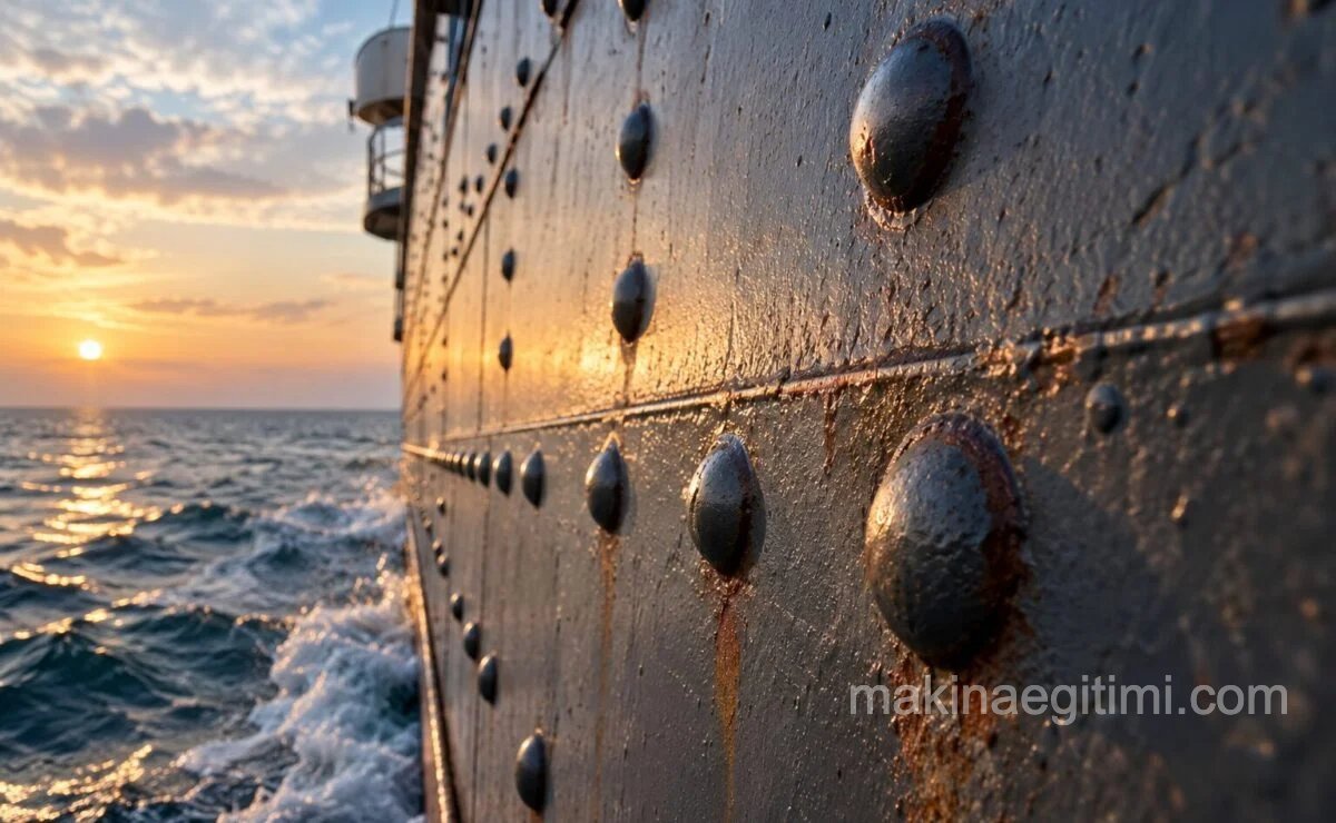
In 1998 Tim Foecke, a metallurgy specialist at the US National Institute of Standards and Technology (NIST), carried out analyses on rivet samples recovered from the wreck. His findings were striking: the wrought iron used in the Titanic’s rivets contained three times as much slag (the glassy residue that forms during metal production) as today’s standards would accept. This excess slag made the rivets far more brittle than normal in the icy waters of the North Atlantic.
What makes it even more interesting is that a deliberate choice of material had been made at the bow and stern sections of the ship. The hydraulic riveting machines of the period could not be fitted into the oval, narrow bow of the ship. For this reason stronger steel rivets were used in the midsection, while softer wrought iron rivets, driven by hand, were preferred at the bow and stern. And by an irony of fate, the place where the Titanic struck the iceberg was exactly that bow section with the weaker rivets.

According to Foecke’s theory, the heads of these brittle rivets snapped off at the moment of impact, the rivets popped out of their holes, and the hull plates separated from one another so that water began to pour in. Another piece of evidence supporting this theory was a set of photographs left from a 1911 collision involving the Titanic’s sister ship Olympic. In these photographs, dozens of empty holes where rivets had popped out of the hull can clearly be seen.
Of course this is not the whole story. Some experts point out that the problem lay less in the material of the rivet than in the fact that only two rivets were used at the point of impact, whereas three rivets would have given a far more durable joint. In other words the issue was not only material but also design. The outcome, though, did not change: one of the smallest and most ordinary pieces of metal had played a decisive role in the greatest maritime disaster in history.
Welding Takes the Stage
Electric arc welding was in fact invented at the end of the nineteenth century, but for years it remained a technology of disputed reliability. In the 1920s some pioneering shipyards began to try welding, but it would take a whole war breaking out for it to genuinely replace riveting.
The Second World War became an unexpected accelerator for welding technology. In order to replace the ships sunk in the Atlantic quickly, the Allied powers decided to mass-produce a standard cargo ship design called the “Liberty ship”. Between 1941 and 1945, more than 2,700 Liberty ships were built in eighteen American shipyards.

The secret of this incredible production speed was welding: riveting made up roughly one third of the total labour cost of a ship, and welding cut that cost dramatically. What is more, welding was a technique that semi-skilled workers could learn within weeks, whereas training a master riveter took years.

One of the cultural symbols of this period was “Rosie the Riveter”. Women who took over the factory jobs left empty as men went to the front became the backbone of wartime production. Around 600,000 rivets were used in the manufacture of a single B-29 bomber, and most of the hands driving those rivets now belonged to women workers.
An Unexpected Penalty: Liberty Ships Break in Two
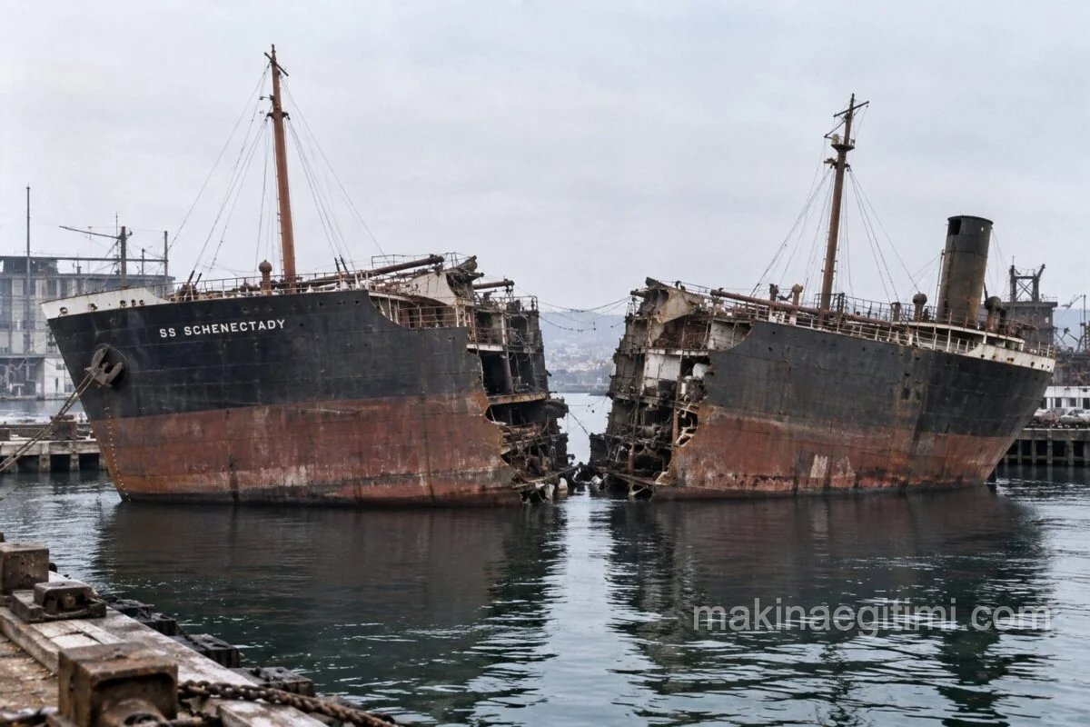
Just at the moment when welding was declaring its victory, history offered an interesting irony. During the war close to 1,500 serious cracking incidents were recorded on Liberty ships, and twelve of them broke completely in two without any warning. The most famous case occurred on 16 January 1943, on the tanker SS Schenectady, which had just completed its sea trials and was lying at a berth in Oregon. The ship suddenly split in two with a crack that could be heard a kilometre away — and it was not even under way.
At first sight the culprits appeared to be the inexperienced workers in the shipyards and the new welding techniques. The real culprit, however, was far more interesting: the steel being used had a metallurgical property that made it unexpectedly brittle at low temperatures, something known as “brittle fracture“. The cold waters of the North Atlantic made the steel almost as brittle as glass.
Constance Tipper, a metallurgy specialist at the University of Cambridge, solved this mystery through her research and proved that the problem arose not from the welding technique but from the quality of the steel being used. But there was another genuinely interesting point here: on the old riveted ships, when a crack formed it usually ran into a rivet hole or a plate edge and stopped there, because a riveted structure was made up of separate panels.
On welded ships, by contrast, the whole hull had become a single, uninterrupted mass of steel. That meant a crack, once started, could spread from one end of the ship to the other without meeting any natural barrier. In other words the “dividedness” provided by the rivet was, unintentionally, a safety feature — and welding had removed it.
Why Did Welding Win Anyway?
Despite these dramatic failures on the Liberty ships, welding did not lose its place in shipbuilding. That is because the source of the problem was not the welding method itself but the quality of the steel being used. The solution was not to give up the welding technique but to develop better steel alloys and to add special reinforcing strips called “crack arrestors” to the hull. Once these lessons had been learned, welding became not only faster and more economical but also, when applied correctly, an even safer method than riveting.
By the 1950s the rivet had almost entirely passed into history as far as large ship hulls were concerned. In heavy steel structures today, welding has completely taken the place of riveting, because it requires no preparation, causes no loss of section and takes up far less room.
Where the Rivet Is Still Alive: the Sky

Interestingly, as rivet technology withdrew from ship hulls it did not become history altogether. Today the fuselage of almost every passenger aircraft still consists of aluminium sheets joined with thousands of rivets. The reason is simple: welding can cause heat-related distortion and weakening of the material in thin aluminium sheets, while the rivet still offers a solution that is both reliable and light in this kind of thin, lightweight structure. The rivet, in other words, lost the seas but still holds the sky.
Related Videos
Conclusion
The move from rivet to weld was not the victory of a single invention but a transformation shaped by decades of trial, error and tragic lessons. While the Titanic’s brittle iron rivets played their part in one disaster, a full century later the welded hulls of the Liberty ships had disasters of their own. Both events, however, left engineering with lasting lessons: material quality can never be neglected, and every new technology brings its own risks with it. That welding dominates on ships today while the rivet still dominates on aircraft is the most concrete proof that the right tool has to be applied to the right job.
Frequently Asked Questions
No. The quality of the rivets was an important factor, but many elements came together to create the disaster: the design of the ship, the height of the watertight compartments, the insufficient number of lifeboats and the speed at the moment of impact.
Although welding began to be tried in the 1920s, the real mass transition took place during the Second World War, in the 1940s, particularly with the Liberty ship programme.
The problem was not the welding technique itself but the fact that the steel being used became unexpectedly brittle at low temperatures. This phenomenon is called brittle fracture, and it was clarified by Constance Tipper of the University of Cambridge.
They are. The rivet is still the preferred method, especially on aircraft fuselages, because thin aluminium sheets need to be joined without the heat damage that welding could cause.
Related Posts
 How Was the Enigma Code Cracked? Alan Turing and the Bombe Machine Explained
 The History of Electric Arc Welding
 The History of the Automobile. The Evolution of Vehicle Technology From Then to Now
 Leonardo da Vinci’s Machines: The Flying, Fighting and Walking Inventions of a Renaissance Genius
 The History and Evolution of Robotics: From Ancient Automata to AI-Powered Robots
 Nazi Germany’s Mega Structures – Super Tanks
 The History of Weaving
 The Story of the Tiger I Tank. The War Machine That Became a Legend