Directional control valves are valves that start, stop, and change the flow direction of compressed air.
How Pneumatic Directional Control Valves Are Represented
Numbers like 3/2 and 5/2 are used to identify directional control valves. The “first number indicates the number of ports on the valve,” and the “second number indicates the number of positions of the valve.”
Number of ports: This is the maximum number of hoses that can be connected to the valve. It is found by counting the number of connections at one position on the symbol.
Number of Positions: This is the number of positions that can be selected on the valve. Each position represents a distinct function performed by the valve. Positions are shown as squares in valve symbols — the number of squares is also the number of positions. Valves have at least two positions: closed-open

In pneumatic circuit diagrams, arrow directions indicate the flow direction of the air passing through the valve. Flow may also pass in the opposite direction of the arrow.

In pneumatic circuit diagrams, ports are indicated with letters or numbers according to the function of the line (pressure line, working line, exhaust line, pilot line).

The figure above illustrates how the air inlet and outlet lines are represented.
2-Position Valves
The simplest directional control valves route airflow between just two states (open/closed).
3-Position Valves
3-position valves, whose middle position can be “closed center” or “open center,” can stop the cylinder at an intermediate position.
Manual Emergency Override
Most industrial valves have an emergency override button so the valve can be actuated manually if power is lost.
Position Types in Pneumatic Directional Control Valves
Normal Position and Working Position
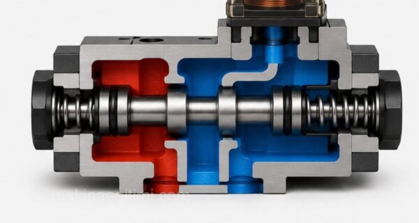
A directional control valve has at least two positions: a normal position and an actuated position (working position). In the normal position of the valve shown in the figure, air cannot pass through. Air coming from the outlet side, i.e., from the working lines, is vented out through the exhaust. When the valve is switched to the actuated position by pressing the button, air is allowed to pass. In this position, the exhaust line is closed.
When we release the button, the valve returns to its normal position as the spring relaxes.
This valve is described as follows: 3/2 normally closed, button-actuated, spring-return directional control valve

Normally Closed and Normally Open Valves
Above, we discussed the normal positions of valves. In directional control valves, whether pneumatic or hydraulic, the position that has not been actuated in some way — by a button, lever, foot pedal, etc. — is the normal position.
If pressure is not supplied to the system in a directional control valve’s normal position, it is normally closed. (See the No. 1 pressure line of the middle valve in the figure alongside)
If pressure can be supplied to the system in the valve’s normal position, it is called a normally open valve. (The first and last valves in the figure alongside)

Spring-Centered Middle Position
In the figure alongside, we see a 5/3 spring-centered middle position. The valve’s normal position is the middle position. For example, the other positions are reached via electrical actuation. When the signal is cut, the spring return brings the valve back to the middle position.


Actuation Methods for Pneumatic Directional Control Valves

Pneumatic directional control valves can change position via manual, mechanical, pneumatic, or electrical actuation. Their circuit diagram symbols are given above.
Related Video
Related Questions
Each square represents a distinct position (state) the valve can take. For example, a symbol with two squares indicates the valve has only two states: open and closed.
The arrow shows the flow direction of the air currently passing through the valve. When the valve switches to a different position, the flow direction can also change, which is why a diagram may show more than one arrow direction.
Related Posts