
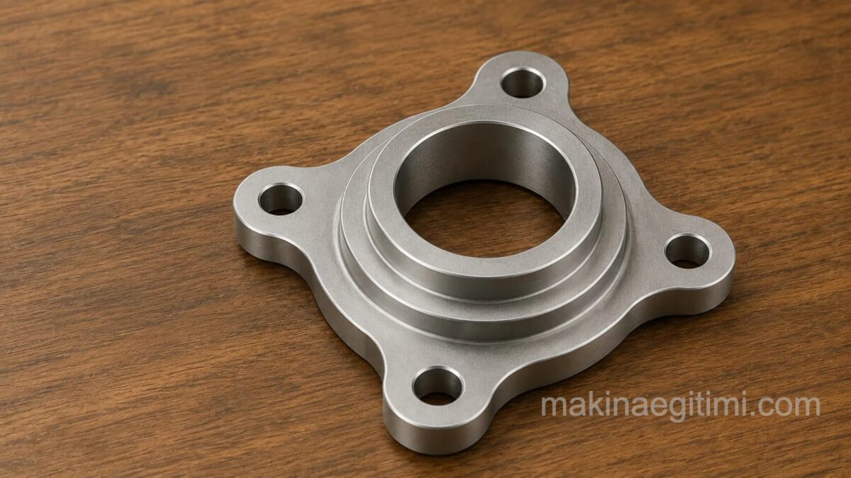
This article contains a sample part for your 2D and 3D drawing practice. You’ll be given step-by-step instructions on how to draw this part. You can also download the CAD files drawn in this tutorial here.

Commands to be used in this drawing: CIRCLE, ARRAY, TRIM, FILLET, EXTRUDE, JOIN, PRESSPULL, UNION, DYNAMIC UCS

STEP 1:
Using the CIRCLE command from the Draw panel on the Home tab, create the circles shown in the figure. Make sure the center of the circle with a radius of 2.5 lies on the circle with a radius of 26.

STEP 2:
Using the Polar option of the ARRAY command, select the two small circles at the top, and select the center of the large circle as the array center point. Enter 4 as the number of items.

STEP 3:
Delete the largest circle and select the FILLET command; now type R on the command line and enter 7 as the fillet radius. Apply the command at the intersection points of the 22.5 circle and the R6 circle, as shown.

STEP 4:
Using the TRIM command, trim away the excess so that it looks like the image alongside.
STEP 5:
Type J on the command line and press enter, then select the entire geometry and press enter again. This joins all the outer 2D segments into a single unit. You may need to repeat the JOIN command a few times to fully join the geometry.
STEP 6:
Change the view to Southwest Isometric and the visual style to Shaded from the Views and Visual Styles panel on the Visualize tab.

STEP 7:
Type PRESSPULL on the command line and click somewhere within the geometry — make sure you click inside the geometry, not on it. Enter the height value (3mm) on the command line and press Enter again.
This command will give the 2D geometry we’ve made so far a thickness of 3 mm. And our drawing will look like this.

STEP 8:
Create a circle with R17 on top of the object made in the previous step, but to create a circle on the top plane you need to make sure Dynamic UCS is turned on. Press F6 to turn on Dynamic UCS, then select the CIRCLE command, move your cursor to the top face, click on the center of the geometry as the circle’s center point, enter a radius of 17 units, and press Enter again.

STEP 9:
Type EXT on the command line and press enter, then select the circle we drew in the previous step and press enter again. Enter a height of 5.5 mm and press enter again to exit the extrude command.

STEP 10:
Create a 14 mm circle on top of the geometry we drew in the previous step and give it a thickness of 3.5 mm using the extrude command.
STEP 11:
Type UNION and press ENTER, then select the entire geometry and press enter again — all the geometry gets merged into a single unit.

STEP 12:
Create an R11 circle on the top surface of the geometry.
STEP 13:
Now type PRESSPULL on the command line and press Enter, then click inside the circle with radius 11 and enter -12 as the geometry depth — this will cut a hole in the existing geometry.

STEP 14:
Type F on the command line and press enter to start the fillet command, then type R on the command line and enter a fillet radius of 1.5 mm. Now select the edge between the flat part and the largest cylinder as shown in the image below, and press enter twice to exit the command. Our shape will now look like the image alongside.
Related Posts
 SolidWorks Assembly Drawings – Live (Rotating) Center
 How Was It Made in SolidWorks – 1
 3D-Print-Ready Cat & Mouse Automaton Toy
 SolidWorks Assembly Work – Transmission System
 SolidWorks Solid Model Exercise-2
 SolidWorks Assembly Drawing Examples – Stuffing Box
 SolidWorks Solid Model Exercise-5 / Loft and Shell
 AutoCAD Solid Model Examples