
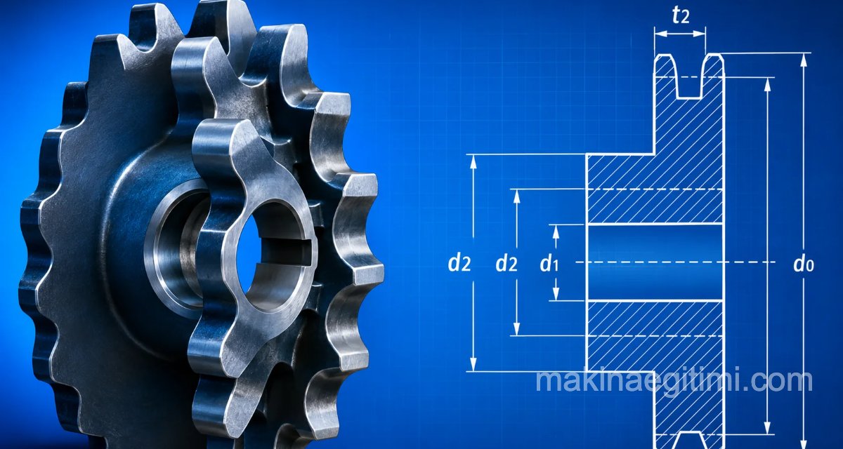
Gear Terminology
To manufacture a gear or a gear pair, it’s necessary to know gear terminology and gear elements. In this section we’ll cover the gear elements: module, pitch, diametral pitch, and circular pitch.
Module (m):
The module is a constant ratio used to express gear sizes in terms of the number of teeth. In the metric system it’s denoted by the letter (m). The module is a ratio obtained either by dividing the pitch by the number Π (m = t / Π), or by dividing the pitch circle diameter by the number of teeth (m = Do/z).
In the formulas, t and Do are in mm. In the metric system, the numerical values of the module are standardized. These values are called module series. (below)

Standard module series used in gear manufacturing.
Note: the ones written in red should be avoided.
In gears whose tooth angle isn’t parallel to the axis but instead makes a certain angle with the axis — for example, helical gears — there is a normal module (mn) and a transverse module (ms).
Pitch (t)
Pitch is the arc length obtained by dividing the pitch circle into z equal parts.
Pitch is also defined as the length on the pitch circle that spans one tooth thickness plus one tooth space.
The distance between the centers of two teeth on the pitch circle also gives the pitch.
Pitch is also known as circular pitch.
It’s denoted by the letter t.

Pitch is obtained by multiplying the module by Π (t = Π.m).
In gears whose tooth angle isn’t parallel to the axis but instead makes a certain angle with the axis (for example, helical gears), there is a normal pitch (tn) and a transverse pitch (ts).

Diametral Pitch and Circular Pitch
In Anglo-Saxon countries (the UK and the US), instead of the module, gear calculations use either diametral pitch (Dp) or circular pitch (Cp). Diametral pitch is obtained either by dividing the number Π (pi) by the gear’s pitch, or by dividing the number of teeth by the pitch circle diameter.

In the formulas above, t and D0 are in inches.
Circular pitch is either the gear’s pitch expressed in inches (Cp = t), or the value obtained by dividing the product of the gear’s number of teeth and the pitch circle by the number Π.

Formulas for Converting Diametral Pitch and Circular Pitch to Module
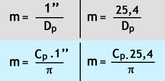
Diametral Pitch and Circular Pitch to Module Conversion Table

Number of Teeth (Z)
This is the total number of teeth on a gear, denoted by the letter (Z). It’s obtained by dividing the pitch circle by the module: z = D0 / m.
Pitch Circle (Do)
This is the circle along which the teeth are divided into equal spacings, denoted by the letter (Do) (see fig. 19.9). In spur gears, the pitch circle is obtained from the product of the module and the number of teeth (Do = m.Z).
Formulas for other gear types are given separately on later pages. Since the pitch is divided into equal intervals along this circle, it’s called the pitch circle.
In a gear pair, the pitch circles are tangent to each other.

Outside Diameter (Da)
This is the diameter of the circle passing through the tips (tops) of the teeth, denoted by the letters (Da). In spur gears it’s obtained from the sum of the pitch circle and twice the module (Da = D0+ 2 m).

Root Diameter (Df)
This is the diameter of the circle passing through the roots (bottoms) of the teeth, denoted by the letters (Df). It’s calculated with a separate formula for each gear type.
Addendum Height (hb)
This is the distance between the tip of the tooth and the pitch circle, denoted by the letters (h^). In gears this height is usually equal to the module (hb = m).
Dedendum Height (ht)
This is the distance between the root of the tooth and the pitch circle, denoted by the letters (ht). In spur gears this height is about 1.166 m (ht = 1.166 x m). In practice, this height varies depending on the gear type and operating conditions. There are hobbing cutters that produce various dedendum heights.
Tooth Height (h)
This is the distance between the tip and root of the tooth. In other words, it equals the sum of the addendum height and the dedendum height (h = hb + ht).
Tooth Space (S)
As the teeth of a gear pair roll against each other while turning, the gap left between the tip of one tooth and the root of the other — in a gear pair whose dedendum height is ht = 1.166 m — this height amounts to h1 = 2 m. In some references this is also called the “working (common) tooth height.”
In a gear pair where the addendum height is hb=m and the dedendum height is pt=1.166m, this space is ht-hb = 1.166m-m=0.166m.
Backlash (Sy)
As the teeth of a gear pair roll against each other while turning, this is the gap remaining between two tooth profiles, denoted by the letters (Sy). Just as every gear has its own backlash, there are also V-gears that operate with no backlash at all.
Working Depth (h1)
As the teeth of a gear pair roll against each other while turning, this is the height formed by the points where the tooth profiles touch each other, denoted by the letter (h1).
In a gear pair with an addendum height of hb = m and a dedendum height of h1 = 1.166 m, this height amounts to h1 = 2 m. In some references this is also called the “working (common) tooth height.”
Definition of Module
The module is a fundamental parameter that determines the tooth size of a gear and is critical for two gears to mesh compatibly.
Tooth Pitch Measurement
Tooth pitch refers to the circular distance between corresponding points on two consecutive teeth.
Standard Pressure Angle
The most commonly used pressure angle in modern gears is standardized at 20 degrees.
Related Questions
The module provides a common reference that expresses gear size in terms of the number of teeth. For two different gears to mesh compatibly, they need to have the same module, which makes the module a critical parameter in gear design.
Since the teeth of a helical gear sit at an angle to the axis, the dimension measured perpendicular to the tooth (normal module) differs from the dimension measured in the plane perpendicular to the gear axis (transverse module). Both of these measurements need to be accounted for separately for the gear to be designed correctly.
Related Posts
 Various Bolt Drawing Examples, Technical Drawings
  AutoCAD Drawings of Machine Parts
  Gear Mechanism Assembly and Detail Drawing
  Formulas for Gear Drawing and Manufacturing
  Dowel Pins – Types and Standards of Dowel Pins
  Vise Technical Drawing – Assembly and Detail Manufacturing Drawing
  Types of Cotter Pins and Dimensional Standards
  Spur Gear Technical Drawings