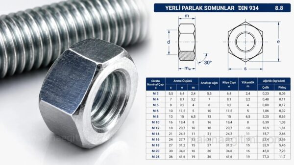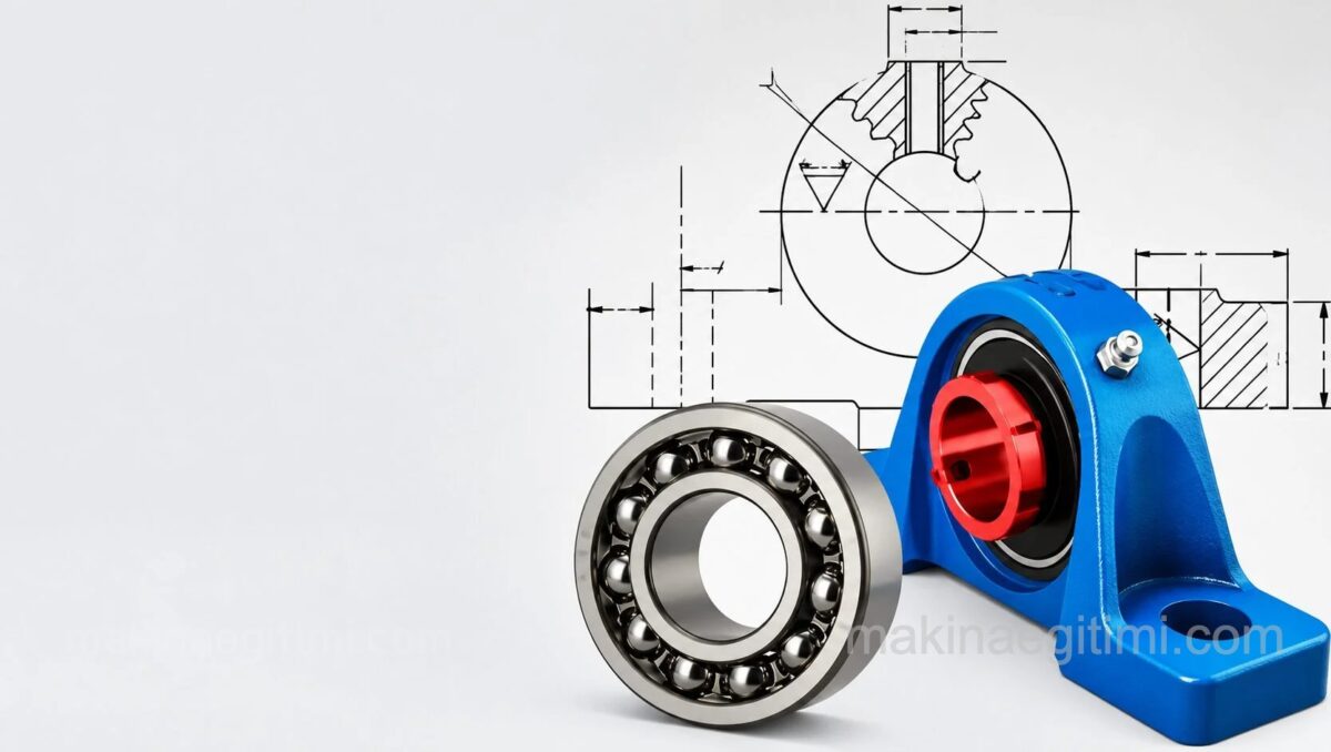

Assembly of rolling bearings
PDF // AUTOCAD DWG

Bearing – construction drawing
PDF // Autocad DWG

Plain Bearings technical drawing
PDF // AUTOCAD DWG

Axial ball bearing (roller bearing)
PDF // Autocad DWG

Plain Bearing Technical Drawing
PDF // AUTOCAD DWG
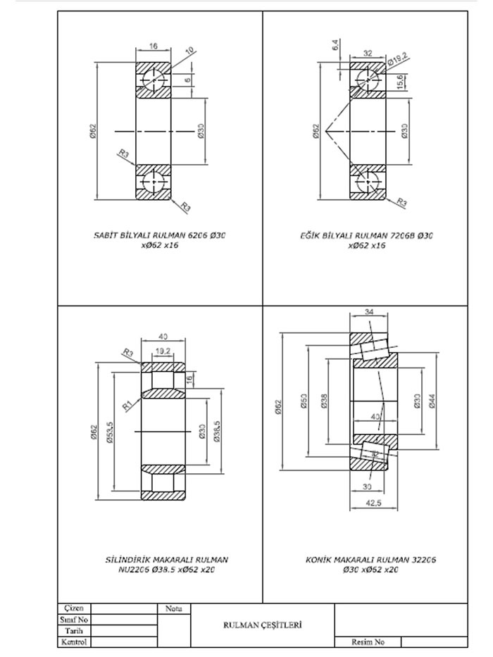
Fixed, angular contact, cylindrical, tapered roller bearing
PDF // AUTOCAD DWG
Bearing Symbols
In technical drawings, rolling bearings are represented with a standard X-shaped symbol to simplify their internal structure.
Scaled Representation
In bearing technical drawings, the outer diameter, bore diameter, and width dimensions are drawn to scale according to standard table values.
Tolerance Specification
Fit tolerances between the bearing and the shaft are specified in technical drawings using ISO tolerance classes (e.g., H7/g6).
Related Questions
Drawing the bearing’s internal details like the balls and cage fully every time takes time and makes the drawing more complex. The standard X symbol simplifies this detail, allowing the drawing to be read more quickly.
If the clearance between the shaft and bearing is too small or too large, the part will either bind or move too much. Specifying this clearance with ISO tolerance classes (such as H7/g6) ties it to a clear standard, ensuring consistency in production.
Related Posts