Compressors are the most important devices used in industry to increase the pressure of gases. A screw compressor is a type of positive-displacement compressor that achieves this using a pair of rotors. Gases are drawn into the compressor using intake valves. They’re made to flow through the rotor and finally discharged from the outlet valve at increased pressure.
The Construction and Parts of a Screw Compressor
The main parts of a screw compressor are as follows:

1- A Pair of Rotors
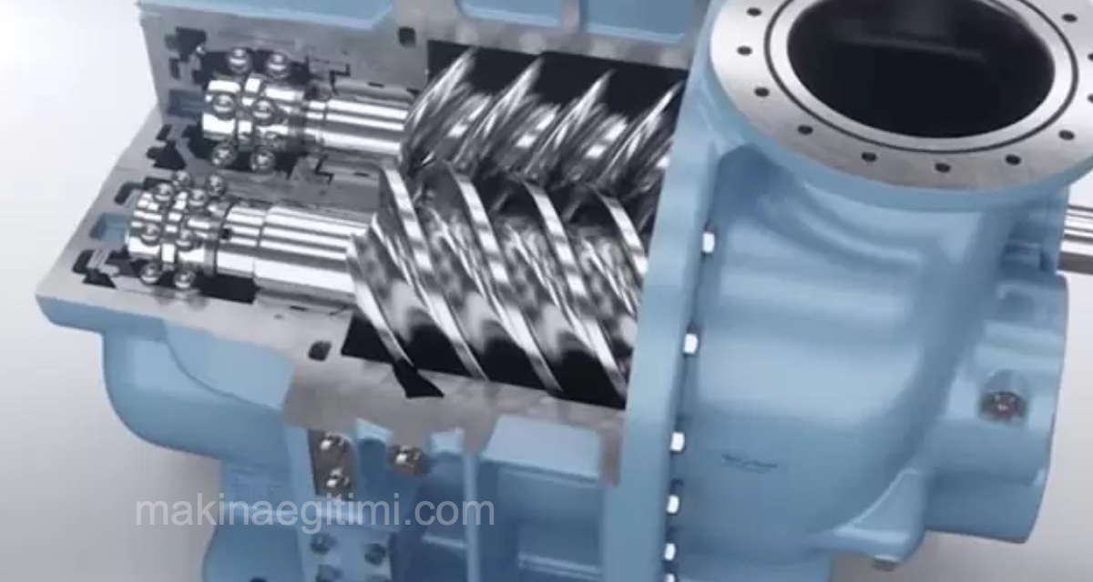
A screw compressor consists of a pair of rotors placed inside a cylindrical chamber. The compression process takes place inside this chamber. Depending on their construction, the rotors can be male or female. The male rotor has lobes, while the female rotor has grooves or flutes. The male rotor generally has four lobes, and the female rotor has six.

The male rotor forms the drive head. The female rotor is the driven rotor.
The rotors are helically grooved along their length. Viewed from the side, this gives them a screw-like appearance. This distinctive look is what gives them the name Screw Compressor.
2) Compression Cylinder
The compression process takes place inside the compression cylinder. The rotor and the other components involved in compression are mounted inside the cylinder. Like an axial-flow compressor, a screw compressor can also be built as a multi-stage unit by combining several cylinders. Each cylinder will have its own rotor assembly.
The compression cylinder also supports the filters and oil lubrication systems.

3) Filters:
The compressor draws in air from the atmosphere, which can contain some foreign particles. The presence of these particles will reduce the overall efficiency of the system. When these substances accumulate on the rotors or other moving components, the machine chokes up and can even stop working. To avoid these extreme situations, we use air filters to clean the intake air. Air filters ensure the compressor machine runs easily and efficiently.
In oil-injected air compressors, the rotor and other compression equipment are bathed in oil. This facilitates proper lubrication and cooling. In these types of compressors, oil filters are used to remove oil from the compressed air.
4) Valves:
Valves are used to draw in raw air and to discharge compressed air from the machine. The intake valves at the top of the compressor draw air in from the tank or the surrounding area. In the case of a screw compressor, the process is continuous, so the device draws in a certain amount of air.
Besides the intake valves, it also has discharge valves. Their function is to release the pressurized fluid from the compression chamber.

5) Storage Tank:
Compressors have tanks to temporarily store the pressurized fluid until it’s delivered to the point of use.
How a Screw Compressor Works
During the intake stroke, the intake valve opens and draws in air from the atmosphere. The air then passes through the space between the male and female rotors. As they mesh and unmesh in a controlled way, the rotors push the air through the narrow spaces created.

As the air reaches the end of the rotors, the volume of the compression chamber keeps decreasing. This reduction in volume causes the system’s pressure to rise.
The moving rotors cause an axial airflow, and the reduction in volume compresses the gas. The airflow has both radial and axial components. In reality, the air travels along a slanted path inside the rotor.
The compressed air is discharged through the discharge valve, whose position depends on the device’s built-in capacity.
Video: How a Screw Compressor Works
Oil-Injected Screw Compressors
Oil-injected screw compressors reduce friction by lubricating the rotors and operate with a longer service life.
Oil-Free Screw Compressors
Oil-free compressors are preferred in applications requiring clean air, such as the food and pharmaceutical industries.
Continuous Airflow
Screw compressors provide a more continuous, pulsation-free airflow compared to piston compressors.
Types of Screw Compressors
Screw Compressor Types by Lubrication and Cooling Method
1) Oil-Injected Screw Compressors
In these compressors, oil completely surrounds the rotor. Although this provides proper lubrication and easily dissipates heat, it can’t be used in areas where oil-free air is required.
Oil-injected screw compressors use oil filters to separate the oil from the air.
2) Oil-Free Screw Compressors
These compressors avoid using oil for lubrication and cooling. They’re very well suited to low-pressure applications and areas that require high-purity air.
However, since there’s no oil for cooling, intercoolers must be used to prevent the air from overheating. Also, compression can only be done in stages. For example, if we need to raise a fluid’s pressure from 2 bar to 7 bar, the process happens in two stages. In the first stage, the pressure is raised to 5 bar, followed by a cooling step. After this cooling step, compression continues, eventually reaching 7 bar in a staged increase.
Screw Compressor Types by Number of Screw Rotors
Twin-Screw Compressor
Twin-screw compressors, more commonly called screw compressors, contain two rotating screws. Depending on the drive and geometry, these rotor screws can be male or female. It has male lobes, and these rotors are driven by a separate motor. The female rotor has grooves, and is driven by the male rotors.
Single-Screw Compressors
Single-screw compressors use a single helical screw to compress air. Two gate rotors surround the helical screw. The sequential meshing and unmeshing pattern of the screw-and-gate-rotor arrangement helps compress the air.

Advantages and Disadvantages of the Screw Compressor
Advantages
- Smooth and continuous service; the compression process with screw compressors is continuous. Intake is done according to demand. These compressors can provide a steady supply of compressed air.
- Quiet devices; these compressors don’t make noise while operating. This is the opposite of other compressors, which make noise from the piston’s motion during compression. The quiet nature of these devices also helps workshop technicians concentrate on other critical equipment in their labs.
- Adaptability; these compressors work well in all kinds of weather conditions. This makes them an easy choice in harsh climate regions.
- Screw compressors consume less oil compared to other oil-lubricated air compressors. As a result, the air at the outlet doesn’t contain excess oil and doesn’t require elaborate filtering processes.
- For the same size, screw compressors can supply more compressed air than a piston compressor. They also operate at a 100% duty cycle, delivering optimal performance.
Disadvantages
- Cost; this device’s initial construction and installation cost can be high. Generally, the cost is far higher than that of piston compressors.
- Maintenance is a critical factor for screw compressors. The oil and filters need to be cleaned and replaced regularly for optimal performance.
- For low-capacity operations, such as below 500 liters, piston (reciprocating) compressors have the advantage over screw compressors due to their lower initial cost and lower maintenance cost.
Related Questions
As the lobes on the male rotor mesh with the grooves on the female rotor while turning, they progressively shrink the volume of air trapped between them. This continuously shrinking volume compresses the air and increases its pressure.
The surface of the rotors is grooved helically, that is, in a spiral, along their length. Viewed from the side, this groove pattern looks just like the threads of a screw, which is why the device is called a “screw compressor”.
Related Posts