
The subject of this article in our machine elements section will be Where are bevel gears used? We’ll try to cover where bevel gears are used through examples. The applications of bevel gears hold a fairly important place for anyone in the machinery sector. They can turn up anywhere motion and force transmission are involved.
Applications of Bevel Gears
Bevel gears can be used to change the drive direction in a gear system by 90 degrees. A good example of this can be shown as the main mechanism of a hand drill. Since the drill handle is turned in the vertical direction, thanks to the bevel gears the chuck rotates around a horizontal axis.


Changing rotation direction in all kinds of motion and power transmission

In the system above, we see the rotary motion taken from the motor (1) being transmitted through a chain (3) after changing its axis of rotation (2).

In the image above, we see a view taken from an old locomotive design. Bevel gears were also used here to transmit motion from the motor to the wheels.

Angle-Changing Function
Bevel gears change the direction of motion by transmitting power between intersecting shaft axes.
Use in the Differential
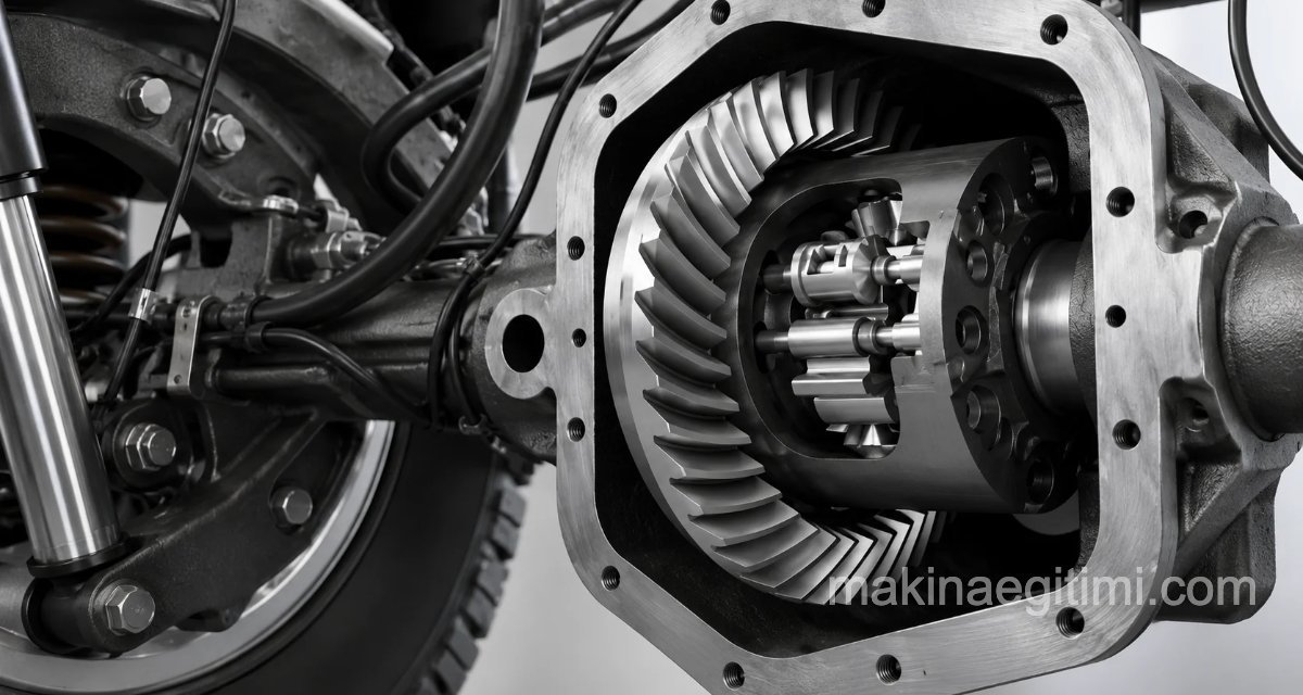
Bevel gears are used in an automobile’s differential system to allow the wheels to rotate at different speeds.
Advantage of Spiral Bevel Gears
Thanks to their curved tooth form, spiral bevel gears run quieter and smoother than straight bevel gears.
Where Are Bevel Gears Used
Mechanical Garage Doors
Electric garage doors use drive gears to rotate or open the door. The gears are placed at right angles to each other and convert the direction of a vertical force into a horizontal force.

Below you can watch an animation of the system shown above in motion.
Motor Vehicle Transmissions

Differential Gear System
Automobiles use differential gear systems to provide two outputs from one input. The differential drive assembly contains at least three bevel gears, and this assembly works perfectly for transmitting torque.

You can click on the images to examine them up close


Helicopter Transmission and Gearbox
We know that bevel gears are mostly used for the purpose of changing the axis when transmitting motion (converting rotation on a horizontal axis into rotation on a vertical axis, or vice versa). We see the finest example of this in helicopters.

Another example of where bevel gears are used is helicopters. For the motion of the helicopter’s rotors to occur, the axis of the motion taken from the engine needs to change. Bevel gears come into play here as well.

Although the rotor mechanism of a real helicopter is actually much more complex, we can see in the image above, taken from a model helicopter part, that a bevel gear is used.

In the image above we see a technical drawing of a helicopter tail rotor gearbox. Note that parts 2 and 3 are the bevel gears that work together.
Motorcycle Engines

Sewing Machine

In the image above we see the mechanism of a Singer sewing machine. A pair of bevel gears was used here. You can click on the image to examine it up close.
As you can see, bevel gears can appear in the working system of many machines we use in our daily lives. If there is rotary motion somewhere and this motion is transmitted elsewhere by changing its axis, we can talk about the presence of a bevel gear there. Who knows, maybe to be sure we could even open it up and take a look, just like in the images above.
In this article, we tried to answer the question Where are bevel gears used? Of course, the places where bevel gears are used aren’t limited to the examples given here. As you might guess, the applications of bevel gears are quite broad. If we’ve managed to broaden your horizons a little on this topic, we’re happy.
Related Questions
While the crank the user turns rotates on a vertical axis, the drill bit needs to rotate on a horizontal axis. Bevel gears make this conversion possible by providing a 90-degree transfer between these two differently oriented rotary motions.
While spur gears can only work between parallel axes, the conical shape of bevel gears also allows power transmission between intersecting axes at different angles. This makes them indispensable in many mechanisms requiring a change of direction, from old locomotives to drills.
Related Posts
 Types of Gears
 Formulas for Gear Drawing and Manufacturing
 Helical Gear Geometry and Strength Calculation
 Making a Wooden Toy with a Cam System – Cat & Mouse
 Compression Spring. Compression Spring Calculation and Drawing
 Screws, Lesson
 Pulley Drawings. Pulleys in Technical Drawing
 Applications of Plain Bearings