In this article we’ll cover what a bevel gear is, where bevel gears are preferred, and what types of bevel gears exist. Here’s the article’s content and topics:
Information About Bevel Gears
Bevel gears are gears used to transmit force and motion between shafts whose axes intersect, with teeth cut around their lateral surfaces so that they converge at the apex of a truncated cone.

In a bevel gear mechanism, the cones assumed to roll on one another are called the pitch cones.

Bevel gears are formed by cutting teeth at equal intervals on the lateral surfaces of a cone whose tip has been truncated parallel to its base.

Bevel gears are generally used in systems where force and speed are transmitted through shafts whose axes intersect. They’re widely used for carrying quite large forces, and in the gearboxes of power machinery and vehicles.
One difference between bevel gears and spur gears is that bevel gears are designed and manufactured together with their mating gear. As with cylindrical spur gears, it’s not enough for the module (or DP) and pressure angle values to match for correct meshing.
In bevel gear manufacturing, extra care is also taken to bring the tooth contact patterns into the correct position. If contact doesn’t occur in the right zone, the gears can’t carry their intended loads and will have a short service life.
Proper bearing support and lubrication are also important when installing bevel gears.
Types of Bevel Gears
- Straight bevel gears
- Skew/Helical bevel gears
- Spiral bevel gears (by tooth curve type: 1-Circular arc / 2-Epicycloid / 3-Involute)
- Zerol bevel gears
Straight Bevel Gears
This type of gear is used to transmit power or torque between shafts whose axes intersect. It’s mostly used in low-speed stages. For example, it’s used in hand-driven stages such as a hand winch or a hand jack. As reference values for peripheral speed, vt = 6 m/s is used for standard gears and vt = 20 m/s for ground gears. The angle between the shafts is generally 90°, though other angles are also possible.


When installing straight bevel gears, care is taken to get the correct angle between the shaft axes and to set the mounting distance correctly. If this isn’t done carefully enough, the tooth contact patterns won’t fall where they should, and as a result the gears won’t be able to carry their intended loads and will have a shorter service life.
Straight bevel gears are frequently used in construction equipment, drilling machines, forklifts, gearboxes, agricultural machinery, textile machinery, automatic door mechanisms, and machine tools.
Helical Bevel Gears
There are also bevel gears whose teeth are still straight, but angled relative to the cone’s axis. This type of gear is called a “helical bevel gear.” Because their contact ratio is higher, they run more quietly and smoothly than straight bevel gears, so they’re used in stages that rotate quickly and carry large torques.


For example: universal gearboxes, machine-tool gearboxes, and similar applications. As reference values for peripheral speed, vt = 40 m/s is used for gears cut on milling, planing, and hobbing machines, and vt = 60 m/s for ground gears.
Spiral Bevel Gears
Spiral bevel gears are also known as a gear-and-pinion (crown-and-pinion) set. The small gear is called the pinion, and the large gear is called the crown (ring gear). The spiral curvature angle relative to the gear axis allows for significant tooth overlap. As a result, the teeth engage progressively, and at least two teeth are in contact at the same time.


Because of this, spiral bevel gears are used in special applications for transmitting large forces, torque, or rotational speed. They can operate at speeds up to 8 times higher than straight bevel gears. They’re specified for operations requiring very quiet running and high root-of-tooth strength.

For example: high-power gearboxes, truck and heavy-equipment gearboxes, and similar applications. As reference values for peripheral speed, vt = 30 m/s is used for gears cut on milling, planing, and hobbing machines, and vt = 60 m/s for ground gears.
Spiral angles are generally between 20 and 45 degrees. However, the most commonly used bevel gear spiral angle is 35 degrees. Also, the minimum number of teeth is generally 12.
Videos About Spiral Bevel Gears:
Computer simulation video of spiral bevel gear manufacturing
Zerol Bevel Gears
Zerol bevel gears (a trademark of Gleason Co.) are similar to straight bevel gears. However, their teeth are curved lengthwise. These curved teeth on Zerol bevel gears are arranged so that the effective spiral angle is zero. Compared to straight-type bevel gears, they generally run more smoothly. They combine the advantages of straight and spiral bevel gears.


Normally, spiral bevel gears can only be run in one direction, but because of their zero spiral angle, Zerol gears can be run in either direction, just like straight bevel gears.
In general, Zerol bevel gears are more resistant to breakage than straight or spiral bevel gears, for the following reasons.
-Their tooth thickness is greater.
-The tooth length of Zerol bevel gears is longer than that of straight bevel gears.
English-language source about Zerol gears:
Tribology Aspects in Angular Transmission Systems Part III-Zerol Bevel Gears / Dr. Hermann Stadtfeld

Straight Bevel Gears
Straight bevel gears are widely preferred in low-speed applications because of their simple design.
Spiral Bevel Gears
Thanks to their curved tooth design, spiral bevel gears run more quietly and can be used at higher speeds.
The Hypoid Gear Difference
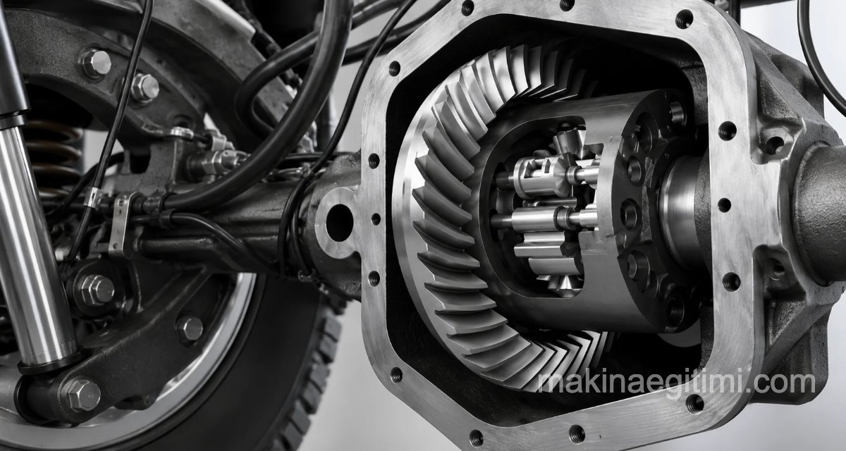
Because hypoid gears can operate with non-intersecting shaft axes, they’re especially preferred in automotive differentials.
Bevel Gear Mechanisms
Right-Angle Bevel Gears
The axes’ point of intersection lies above the surface of the larger gear’s pitch circle. The shaft angle is Σ = 90o ( δ 1 + δ 2 = 90o ).


Internal (Re-Entrant) Bevel Gears
The point of intersection lies below the surface of the pitch circle. This is a rarely used type of gear. Gears whose shaft angle is greater than 90°: shaft angle Σ > 90 ( δ 1 + δ 2 > 90 ).


External (Acute-Angle) Bevel Gears
Gears whose shaft angle is less than 90°: shaft angle Σ < 90 ( δ 1 + δ 2 < 90 ).


Hypoid Gears
Bevel gears whose axes don’t intersect are called a hypoid mechanism. They’re generally used to connect drive shafts to automobiles’ rear axles, and are often incorrectly called spiral gears.
Because hypoid gears have additional sliding motion in the direction of tooth width (sliding contact), their efficiency is lower than that of gears with intersecting axes.


Hypoid bevel gears can be seen applied in automobile differentials.
Scientific Papers About Bevel Gears
- Bevel Gears / Vedat Temiz / Istanbul Technical University, Faculty of Mechanical Engineering
- Computer Simulation of Involute Bevel Gears / Cüneyt Fetvacı – Istanbul University, Faculty of Engineering
- Bevel Gears – Presentation / Prof. Dr. Mehmet Fırat
- Bevel Gears – Comprehensive PDF Document / M. Güven Kutay
Related Questions
While spur gears can only work between parallel axes, the cone-shaped design of bevel gears makes it possible to transmit power and motion between angled, intersecting axes as well. This is essential wherever power transmission needs to change direction, such as in a vehicle’s differential.
Unlike spur gears, it’s not enough for bevel gears to simply match in module and pressure angle; the tooth contact patterns also need to be in the correct position. This precision can only be fully achieved when the two gears are designed and matched together.
Related Posts