
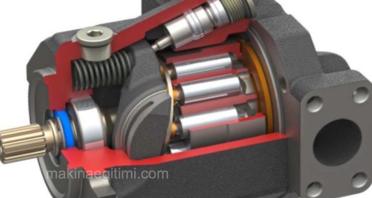
If you’re wondering what the types of hydraulic pumps are, read on. Hydraulic pumps are generally divided into three types based on their construction: gear, vane, and piston pumps:

Before getting into the types of hydraulic pumps, for a comprehensive information page covering what a hydraulic pump is, how its working system works, how efficiency calculations are made, and what should be considered when selecting a pump, SEE: Hydraulic Pump
Gear Pumps
These are either external-gear or internal-gear. Gear pumps have a simple structure, consisting of two spur gears meshing smoothly with each other.
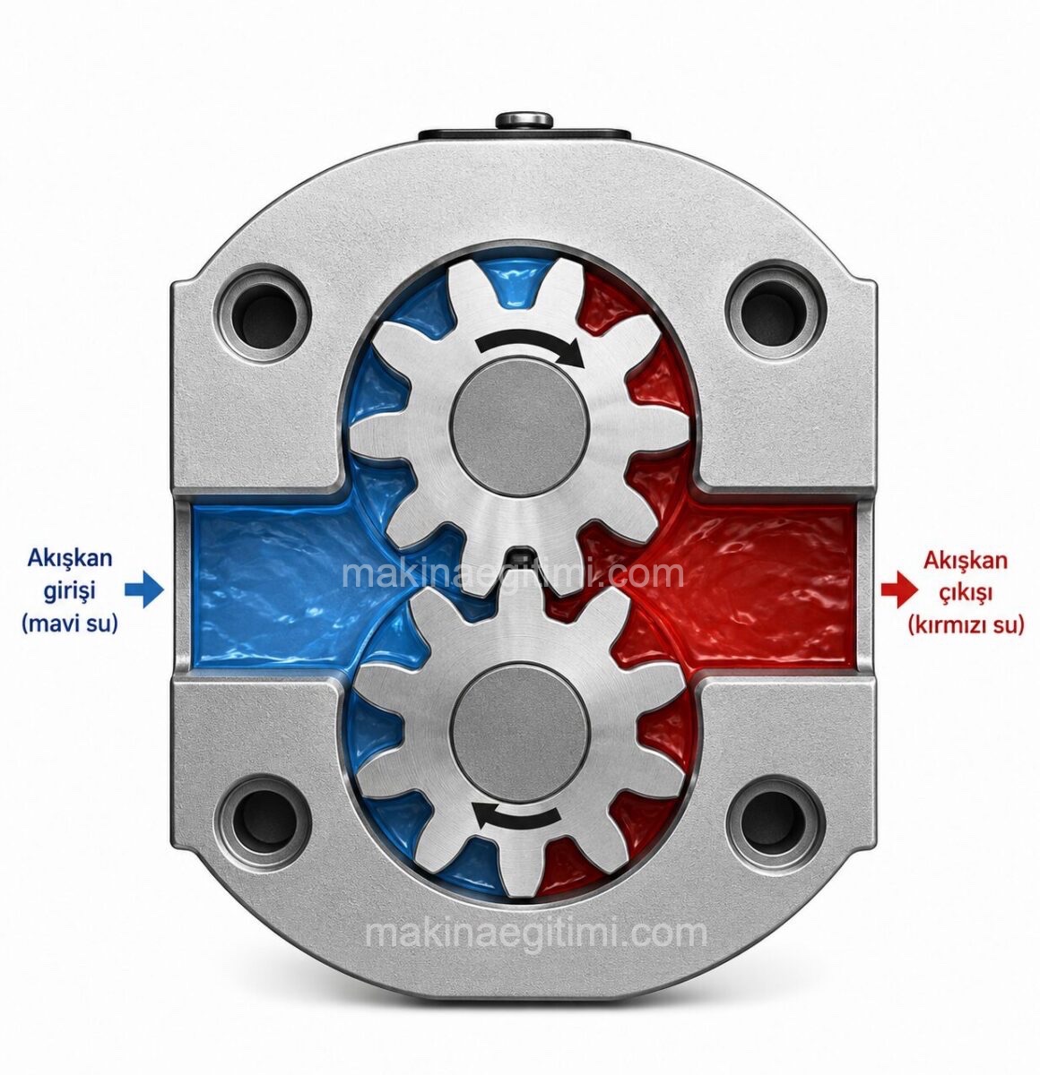
Oil drawn in from the suction line is captured between the gear teeth and delivered to the pressure line. The diameter of the gears and the tooth depth affect the volume of flow they’ll deliver.
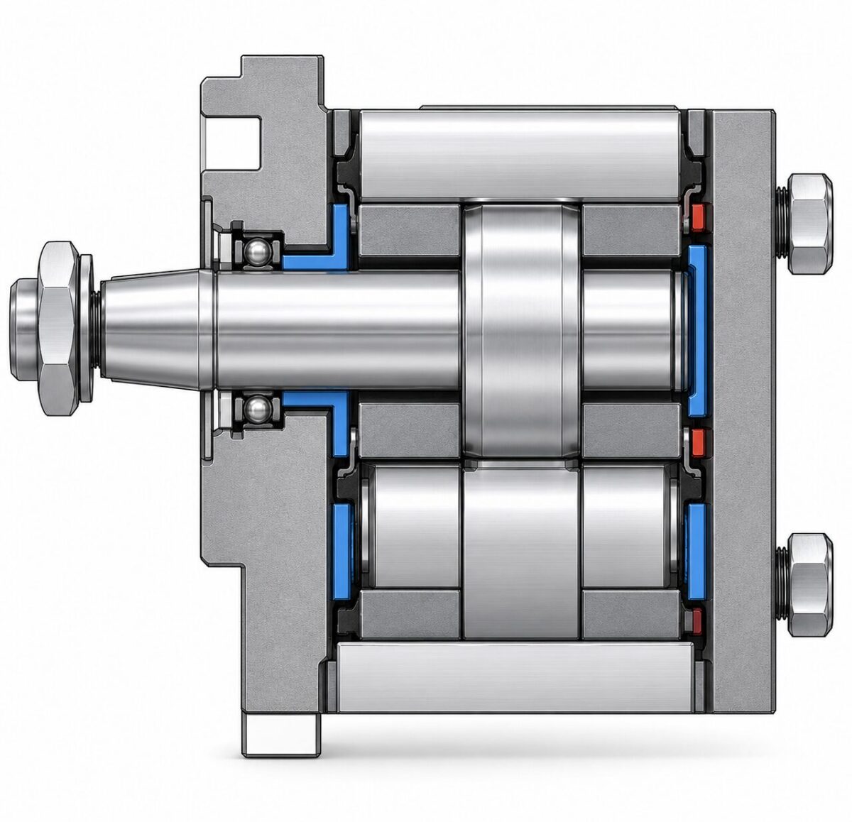
Gear hydraulic pumps are made in various capacities and sizes. Selecting a pump with the appropriate capacity for the system, and the manufacturer’s recommendations on this topic, should be taken into account. For gear pumps with working pressures between 40 bar and 250 bar, flow rates can also range from 3.5 cm³/rev to 100 cm³/rev.
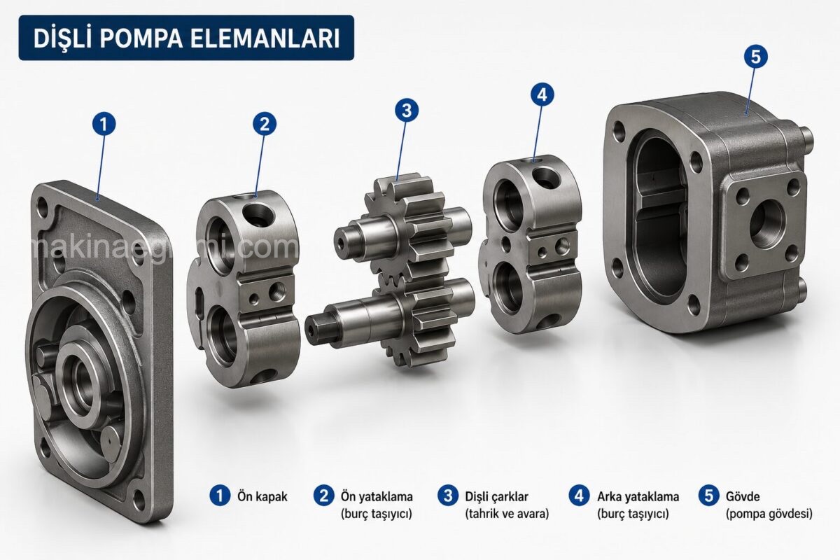
Reasons for their preference include: the simplicity of gear pumps’ construction, their high suction lift, a speed range varying from 1400 rpm to 2800 rpm, their high overall efficiency, and the fact that they can be comfortably used in dusty and dirty environments.
Gear pumps can be made as tandem 2-, 3-, or 4-section units.
The pumps’ gears and shafts are made of case-hardening steel. Needle bearings are used at the bearings.

Flow Rate Calculation for Gear Pumps:
In gear pumps, flow rate varies with the gears’ rotational speed, pitch circle diameter, tooth height, and tooth width.
These values are also taken into account when calculating flow rate.
Q = b.d.h.W
Q = Gear pump’s flow rate…….. cm³/second
h= Tooth height …………..cm
b=Tooth width ………….cm
W= Angular velocity ……………radians/sec
d=Pitch circle diameter ……..cm
.
External-Gear Hydraulic Pump:
As shown in the figure, on the suction side, the pump’s teeth separate from each other, producing volume growth (a void) and drawing in oil. On the discharge side, the teeth mesh with each other, producing volume shrinkage and delivering the oil under pressure.
Internal-Gear Hydraulic Pump
As shown, the gears are positioned eccentrically, one inside the other. The outer gear has one more tooth than the inner gear. As the outer gear drives the inner gear, the hydraulic pump performs suction and discharge.
Internal-gear pumps operate at lower speed and pressure compared to external-gear ones.
- They can operate continuously at 315 bar, and briefly at 350 bar
- They run very quietly
- They’re generally suitable for industrial applications.

–
Internal eccentric-gear hydraulic pumps are used where large flow rate and low operating pressure are required in the hydraulic system. In this type of pump, the direction of flow can be reversed — when the direction of rotation changes, the suction and discharge directions also change.

Gear Pump Simplicity
Thanks to their simple construction and low cost, gear pumps are the most widely used hydraulic pump type in industry.
Vane Pump Efficiency
Vane pumps offer high efficiency and relatively quiet operation in medium-pressure applications.
Piston Pump Pressure
Piston pumps are the pump type that can reach the highest pressure values and provide precise flow control.
Vane Pumps
Vane pumps consist of a housing (cam ring) inside which a circular rotor is placed eccentrically, and vanes mounted around the rotor’s circumference. As the rotor turns, the vanes, which move within their slots, touch the housing due to centrifugal force as they rotate, and slide in and out of their own slots according to the eccentricity. The rotating vanes carry along the oil they draw in and deliver it to the pressure line.
–
The working principle of vane pumps is no different from gear pumps.
The oil drawn in is delivered from one side to the other as a result of a volumetric shrinkage. Vane pumps, which are suitable for medium pressures, have high starting speeds.
–
Since vane pumps have a precision construction requiring more machining work, they’re more expensive than gear pumps.
Properties of Vane Hydraulic Pumps
1-Mounting dimensions are small.
2-They run vibration-free and quiet,
3-They’re suitable for working pressures up to 160 bar.
4-The flow rate that can be achieved ranges between 180 liters/min and 450 liters/min,
5- They operate between 900 and 3000 rpm.
6- Since the vanes are pressed against the housing by centrifugal force, sealing is achieved.
7-They require more machining work than gear pumps.
8-Their operating pressures are lower than other pumps.
9-Their internal leakage is greater than gear pumps.
10. Their efficiency is low. (70% – 75%)
11-. Friction losses and heating are high.
12. Oil with suitable properties must be used.
Piston Pumps
These are divided into two types: axial piston pumps and radial piston pumps.
Axial piston pumps in turn are divided into three: a) swash-plate pump b) bent-axis pump c) hand pump.
Axial Piston Pumps
In these pumps, the pistons are placed parallel to the pump axis.
a) Swash-Plate Axial Piston Hydraulic Pump
Pumping motion is provided by the swash plate. Free pistons, rotating together with the cylinder block, move back and forth as they pass in front of the fixed swash plate.
When the pistons face the inlet port on the valve plate, suction occurs; when they face the outlet port, discharge occurs.

In a swash-plate pump, the amount of oil delivered per unit time (flow rate) is changed by adjusting the swash plate’s tilt angle. If the angle is large, the piston stroke also grows and the flow rate increases. If the angle is small, the piston stroke also shrinks and the flow rate decreases
When the angle is zero, the plate isn’t tilted, and since the stroke will also be zero, no suction-discharge occurs
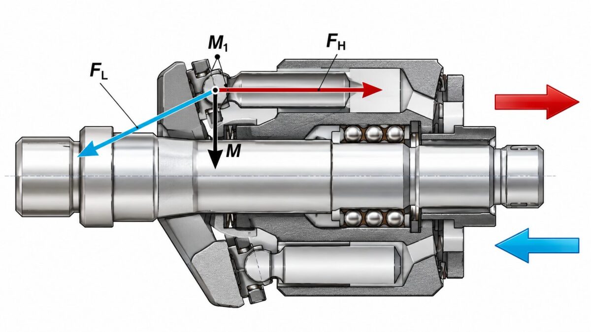
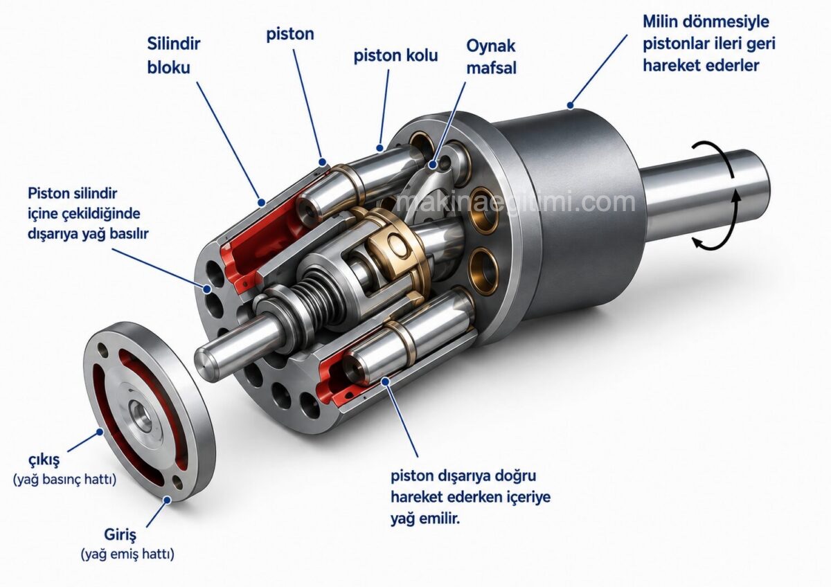
b) Bent-Axis Axial Piston Hydraulic Pump
In this hydraulic pump, instead of a swash plate, the pumping action is created by tilting the cylinder block (g) itself. When the pump shaft (f) rotates, the articulated pistons (a) are forced to move back and forth in the cylinders (b) inside the tilted rotating block. The valve plate (c) in front of the cylinder block (housing) allows oil to be drawn in from the inlet port (d) and discharged from the outlet port (e).
Radial Piston Pumps
In these pumps, the cylinders (pistons) are arranged so their axes intersect.
- They can operate at very high pressures, such as 700 bar
- They’re low-displacement pumps.
- They’re used for compression rather than filling operations.
- They’re suitable for industrial applications

The pistons are articulated at one end around the inner circumference of the housing ring. The housing ring and the block containing the cylinders are mounted eccentrically relative to each other. When the hydraulic pump‘s shaft rotates the cylinder block, the pistons follow the ring’s surface, causing them to move in and out of the cylinders. This is how pumping is achieved.
As is known, in axial pumps the pistons perform the in-and-out motion; in radial pumps, since the cylinders themselves are eccentric, the cylinders perform that same motion. When the cylinders
face the inlet port on the valve plate, suction occurs, and as they rotate to face the outlet port, discharge occurs.
Piston Hand Pumps
In these pumps, the piston’s operation (suction-discharge motion) is done by hand control. For this reason, pressure and speed aren’t sufficiently regular in hand pumps. Hand pumps are used in simple circuits and as a backup.
The pump’s power depends on the person using it.
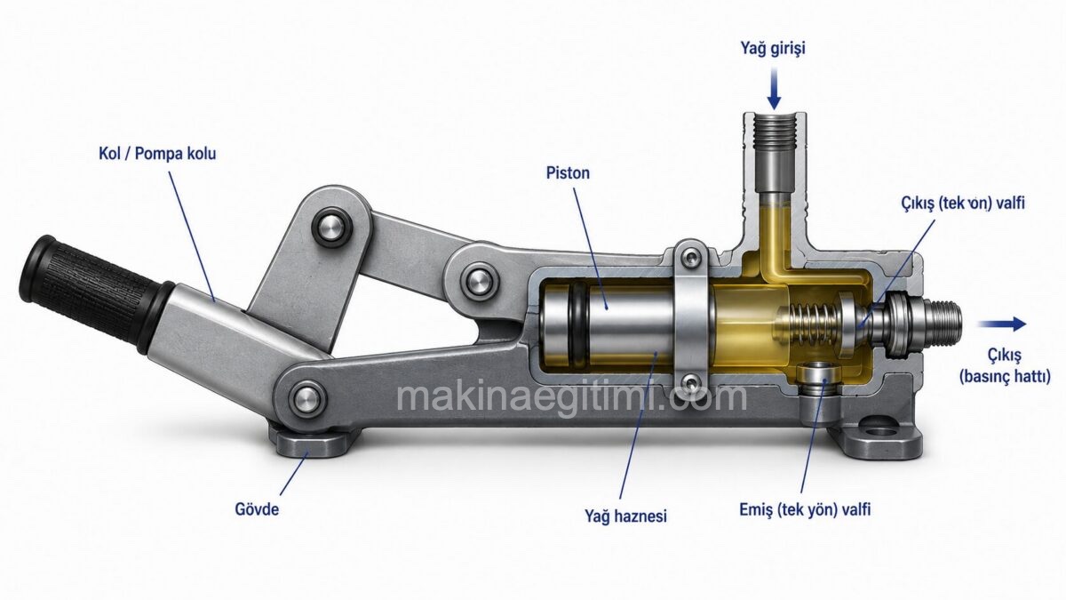
The hydraulic hand pump is installed in parallel with the gear pump in the system. If for any reason the gear pump goes offline, or in the event of a sudden power loss, a hand pump can be installed in parallel with the circuit to prevent an accident and protect the system.
Oil drawn from the reservoir via a check valve is passed through the piston and sent under pressure to the system during discharge. Since terrible accidents would occur if an aircraft’s landing gear failed to deploy for any reason, this type of hydraulic pump is used and the system is made fail-safe. This type of pump can also be used in the manufacturing of hydraulic presses and in jacks.

Types of hydraulic pumps / piston hand pump (jack)
As long as the hand pump’s operating lever is moved back and forth, oil drawn in from the suction line on the right end is delivered to the pressure line on the left. By placing either a ball or a conical-tipped piece inside the piston, one-way flow can be achieved during suction and discharge.
Hydraulic Hand Pump in Aircraft Landing Gear
In a hydraulically operated system, pressurized fluid can be obtained via a gear pump.
However, if the pump goes offline for any reason, a hand pump can also be connected in parallel so the system can continue performing its functions and prevent accidents.
This type of setup is very common in the aviation industry. The hydraulic system that operates the landing gear absolutely must work. In such places, a manually operable hydraulic pump is used for safety purposes
Related Questions
The diameter of the gears and the tooth depth directly determine how much fluid is carried with each revolution. Larger-diameter or deeper-toothed gears carry more fluid to the pressure line at the same rotational speed.
The pump works simply by the rotation of two meshed gears; it doesn’t contain complex moving parts. This simplicity both lowers manufacturing cost and makes the pump easy to maintain and reliable.
Related Posts
 Elements of a Hydraulic Cylinder
 Time Delay Valve Explanation and Applications
 Safety Rules for Workers on Hydraulic and Pneumatic Machines
 What Are the Differences Between Hydraulic and Pneumatic Systems?
 Maintenance and Repair Recommendations for Hydraulic Circuits
 3-Way, 2-Position (3/2) Directional Control Valves
 Hydraulic Pressure Line Filter Explained
 AND Valve Explanation and Applications