
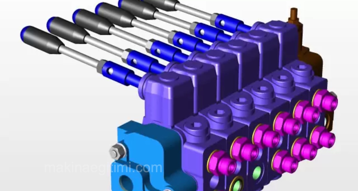
Machine technology / Hydraulics-pneumatics. We use directional control valves to make an actuator in a hydraulic system move forward-backward or left-right, or to reverse its direction or stop it whenever we want. Directional control valves let us control the direction of the fluid going to the actuator however we like, and hold it wherever we want.
Ways and Positions in Directional Control Valves
The number of connections made to a directional control valve is called the number of “ways.” If the fluid coming from the pump goes to the cylinder and moves the cylinder forward (+), and the fluid coming out of the cylinder passes through the valve and returns to the reservoir, then four connections have been made. In that case, this directional control valve is a 4-way (four-way) directional control valve.

Without changing the connections on a directional control valve, changing the fluid’s direction (and therefore the direction of the actuators — cylinder, hydraulic motor) or stopping it, by means of a change made to the valve’s spool or rotary element, is called switching position on the valve.
A directional control valve is described first by its number of ways and then by its number of positions. A slash is placed between the two figures. For example, when we say a 4/2 directional control valve, this is understood to mean a four-way, two-position directional control valve.
How Directional Control Valves Are Named
Directional control valves are named, in order of priority, based on: 1). The number of ways, 2). The number of positions, 3). The way the valve is actuated, 4). The valve’s method of construction.
For example: 4/2 manually operated, spring-return directional control valve. If the valve has three positions, the state of the valve’s center position is also specified.
The connections made to valves are indicated with letters or numbers.
If letters are used, the line coming from the pump is (P), the line going to the reservoir (tank) is (T), and the lines going to and coming from the actuators are indicated with letters like (A, B). The signal inputs that actuate the valve are indicated with X, Y. If numbers are used, the pump (1) and reservoir (3) are indicated with odd numbers, while the connections going to the actuators are indicated with even numbers like 2, 4.
Signal connections, on the other hand, are indicated with numbers like 12, 14, which show which signal brings the valve to which position and which output is obtained from which input. The figure below shows the lettering and numbering of the connections on a valve.

As can be understood from the figure, the fluid coming from the pump (P) goes from outlet A to the cylinder, and the fluid coming from the cylinder passes through (B) and goes to the reservoir (tank). Signal X produces this position. In the numbering scheme, the fluid coming from the pump (1) goes to the cylinder from outlet no. (2), and the fluid coming from the cylinder passes through (4) and goes to the reservoir (tank) via path no. (3). Signal 12 produces this position on the valve. If signal 14 is applied to the valve instead, the fluid (1) coming from the pump will pass through path no. (4), and the cylinder will move in the opposite direction compared to the first position.
What “Number of Ways” Means
Directional control valves are classified by their number of connection ports, such as 2-way, 3-way, or 4-way.
Importance of the Number of Positions
The number of positions of a valve indicates how many different ways the flow can be directed (for example, 2-position, 3-position).
Electrically Actuated Valves
Solenoid (electrically) actuated directional valves can be controlled automatically by control systems such as PLCs.
Classification of Directional Control Valves
We can divide directional control valves into two groups based on their method of construction:
- Spool-type directional control valves
- Rotary-type directional control valves
Both types of valve are widely used in hydraulic systems. Although their construction differs, if both valves have the same number of ways and positions, their symbolic diagrams are the same. A spool-type directional control valve changes position through the back-and-forth motion of the spool. A rotary-type directional control valve changes position by rotation of the rotating
element (rotor) inside the valve. The figure below shows the sectional and symbolic view of a spool-type 4/3 directional control valve and the forward-backward motion of the cylinder.

When the 4/3 directional control valve is in position (a), the fluid coming from the pump passes through the valve and enters the cylinder, and the piston moves forward (+). When the valve is in the middle (o) position, the piston stays where it is, because the fluid entering the valve returns straight back to the reservoir. If the valve is switched to position (b), the fluid entering the cylinder from the other side moves the piston backward (-).
The figure below shows a rotary-type directional control valve and how it works.

Types of Directional Control Valves
We can group directional control valves used in hydraulic systems as follows:
Directional control valves by construction type
- Spool-type directional control valves
- Rotary-type directional control valves
Directional control valves by number of ways and positions
- 2-way, 2-position directional control valves
- 3-way, 2-position directional control valves
- 4-way, 2-position directional control valves
- 4-way, 3-position directional control valves
Directional control valves by method of actuation
- Lever-operated valves
- Mechanically actuated valves
- Electrically actuated valves
- Hydraulically actuated valves
- Electro-pneumatically actuated valves
All valves used in hydraulic systems are found in one of two states when ready for use.
- Normally open valves
- Normally closed valves.
Normally Open Valves
If the fluid coming from the hydraulic pump enters the valve’s inlet and passes through the outlet path to reach the system, such valves are called normally open valves. The figure below shows a normally open valve.

normally open directional control valve
NORMALLY CLOSED VALVES
If the fluid coming from the hydraulic pump into the valve cannot pass through the valve, such valves are called normally closed valves. To obtain output from a normally closed valve, the valve’s position is switched by pressing its operating lever or button. This produces flow at the valve’s outlet. The figure below shows a normally closed valve.

normally closed directional control valve
Related Questions
The first number (4) indicates the total number of connections made to the valve, i.e. the number of “ways.” The second number (2) indicates the number of different “positions” the valve can take, i.e. how many different ways the fluid can be directed.
When the spool or rotary element inside the valve is moved, the path between the fluid’s inlet and outlet connections changes. This change makes the fluid coming from the same pump move the cylinder in the opposite direction compared to before.
Related Posts
 What Is a Hydraulic Accumulator Used For
 4-Way 3-Position Directional Control Valves
 4-Way 2-Position Directional Control Valves
 How Does a Hydraulic Jack Work?
 The Importance and Applications of Hydraulics and Pneumatics
 Basic Components of Pneumatic Systems
 What Is a Hydraulic Return Filter. Return Line Filters
 What Is a Suction Filter? SUCTION LINE FILTERS