
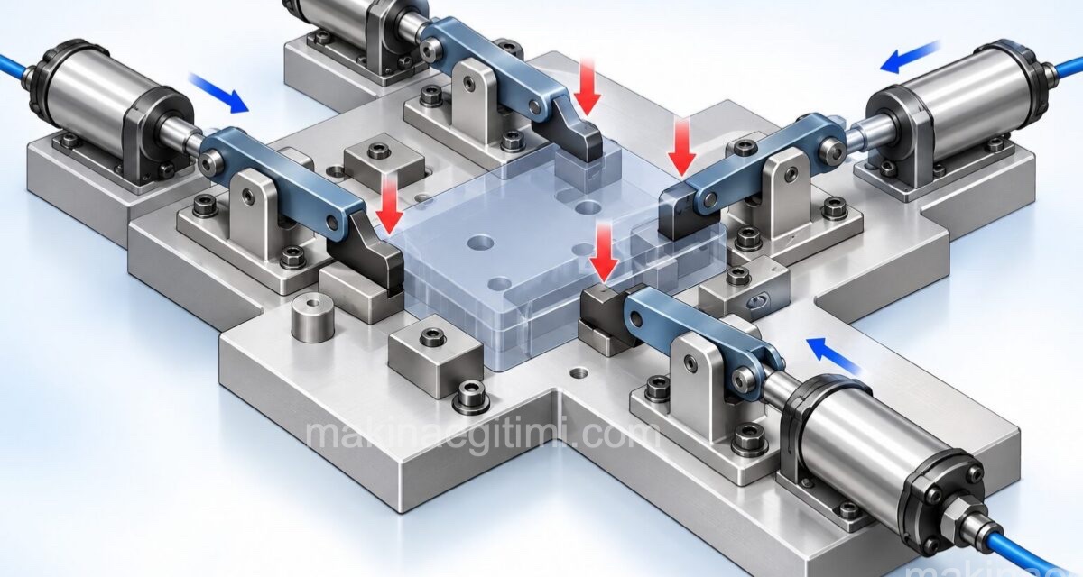
We’ve dedicated this article to simple and industrial pneumatic application examples. We’ll take a look at the application areas of the valves, cylinders, and various pneumatic circuit elements we’ve seen in our pneumatics lessons. This way, we’ll be answering questions like: Where is pneumatics used? Or, what are the everyday application areas of pneumatics? We’ll examine the circuit diagrams of sample pneumatic applications. These pneumatic circuit examples, which we’ve tried to make as varied as possible below, can give you ideas for building different pneumatic systems and broaden your understanding of how pneumatic circuit elements are used.
Simple Pneumatic Application Examples
In this section, we’ll look at what we can call simple examples — systems generally made up of one valve and one cylinder. Although quite simple compared to the level of complexity pneumatic systems and pneumatic circuits can reach, these systems are among the examples where the logic of pneumatic operation and how a pneumatic circuit works can be understood most easily.
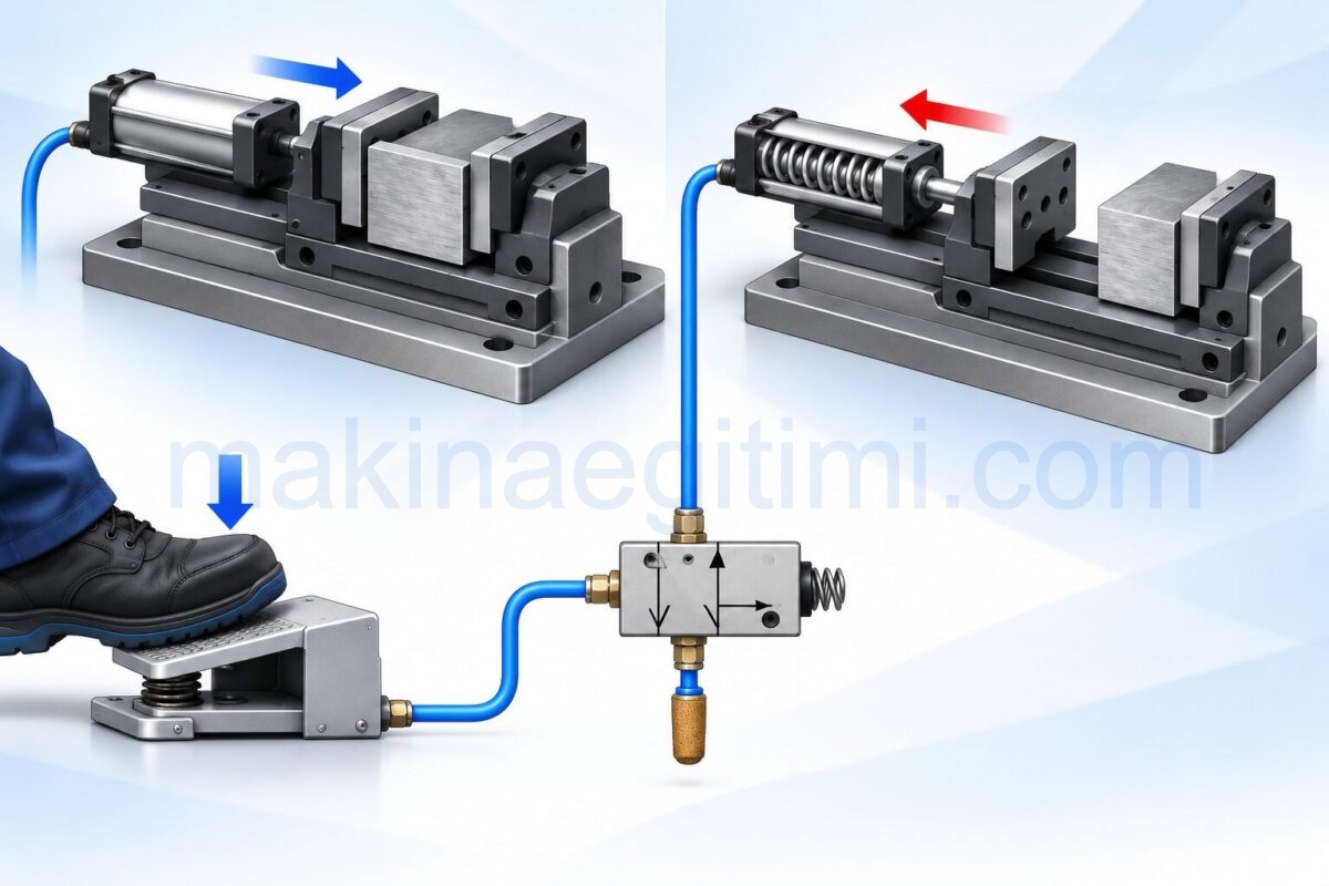
Pneumatic Vise
The pneumatic vise shown below runs on compressed air. A three-way, two-position (3/2) valve is used to supply compressed air to the single-acting, spring-return cylinder. When the pedal is pressed, the vise clamps the workpiece; when the foot is released from the pedal, the workpiece is released.
Sample Circuit Diagram of a Pneumatic Vise
The pneumatic circuit example given in the diagram alongside includes 1 pedal-operated, three-way two-position (3/2) directional control valve. The valve has a spring return.
In the valve’s normal position, the air inside the cylinder is exhausted through the A-R line. Air pumped from the compressor cannot reach the cylinder. As a result, the piston stays retracted (the vise is not clamped).
When the valve is actuated by the pedal, the air pumped from the compressor fills the cylinder and pushes the piston forward. The exhaust line is now closed. The vise is clamped.
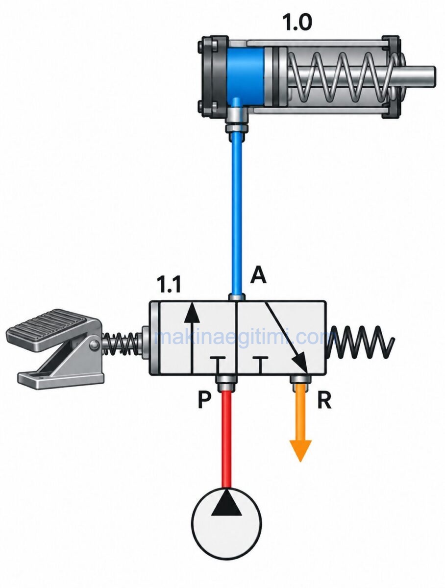
When we stop pressing the foot pedal, the valve returns to its original position thanks to its spring return, and the air in the system is exhausted (the vise jaws release).
Pneumatic Application Example 2
By making use of a pneumatic system, a simple setup like the one shown below can be built to allow flow to be throttled to a desired amount, or shut off completely. In the middle position of the three-position valve, flow is completely shut off; in the other two positions, flow is set to different amounts.

Sample Application Circuit Diagram

Let’s look at what happens in the circuit diagram of the sample pneumatic application alongside. There is a 4-way, 3-position (4/3) lever-operated, spring-return directional control valve connected to a cylinder.
In the valve’s normal position, both the pressure line and the return line are closed. As a result, there is no movement in the piston. Also, since flow to the return line isn’t free, the piston cannot be actuated.
When the valve is moved to position 1 by the lever, the pressure and return lines open. Compressed air follows the P-A path and fills the cylinder. The piston moves to the right.
When the valve is moved to position 3 by the lever, this time the air in the cylinder is exhausted via the A-R path. Air pumped from the compressor fills the right-hand side of the cylinder via P-B. The piston moves to the left.
When the lever is released, thanks to the spring return the valve returns to the middle position and the piston stops moving. It stays wherever it is. If we think of this system as a vise, the vise jaws stay fixed unless the lever is moved, and the vise jaws open and close as the lever is moved.
Industrial Pneumatic Application Examples
Using a pneumatic system, it’s possible to clamp and release workpieces easily and quickly. A few simple elements are enough for these operations. As shown below, air sent to single-acting cylinders through (3/2) valves pulls the gripper down to clamp, and the workpiece is fixed in place. When the air supply to the cylinder is cut off, the gripper returns to its free position under spring action and releases the workpiece.
Clamping Two Workpieces at the Same Time With a Pneumatic System

A system and circuit diagram where two workpieces are clamped at the same time (above)
Bending Machine

A pneumatic circuit used to bend a workpiece using three separate cylinders
In the pneumatic system shown above, air is supplied by the leftmost valve to cylinder no. (1), which clamps the workpiece. When air is admitted into the circuit, the air entering cylinder no. (1) first clamps the sheet-metal part. As the cam seen below moves to the right, the spool of the (3/2) valve in the middle rises and moves to the open position. Compressed air passing through this valve goes to cylinder no. (2) and performs the first bend.
As the cam continues moving to the right, the spool of the rightmost (3/2) valve hits the cam, rises, and switches from the closed position to the open position, allowing compressed air to reach cylinder no. (3). This cylinder performs the final bending operation. As the cam moves back in the opposite direction (2), first piston (3), then piston (2), and then piston (1) are retracted, and the workpiece is ejected.
Clamping and Fixturing Die

A clamping and fixturing die operated by pneumatic power

The circuit diagram of the pneumatic clamping and fixturing die is a great example of a pneumatic application.
In the pneumatic workpiece-clamping die shown above, when compressed air is supplied to the cylinders, the pistons extend and push the wedge, which has an angled surface under the rollers, forward. In doing so, the workpiece placed inside the die is clamped by means of a linkage mechanism. Since the cylinders are single-acting with spring return, as soon as the compressed air is cut off, the pistons retract immediately and the workpiece is released. This makes it possible to fixture a workpiece with a large surface area in a short time.
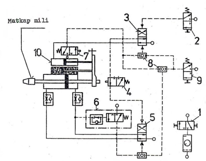
Circuit diagram of the pneumatic elements making up the automatic feed unit.
| 1-Air inlet 2-Start button 3-(4/2) valve 4-(3/2) valve . 5- (4/2) valve | 6- Timer valve 7- (3/2) valve 8-(OR) valve 9- (3/2) valve 10- Air cylinder of the pneumo-hydraulic feed unit |
Pneumatic Drilling Machine

When the start button is pressed on a workpiece being drilled on a pneumatic drilling machine, when the drilling piston hits the limit switch at the end of its stroke, the drill will automatically retract and wait ready for the next operation. The pneumatic circuit diagram for this system:

Related Posts
 Classification of Hydraulic Oils. Types of Hydraulic Oil
  What Is Pascal’s Principle? Where It Is Used
  What Is a Hydraulic Pump. How Does It Work?
  Calculating the Moisture Content of Compressed Air
  3-Way, 2-Position (3/2) Directional Control Valves
  Hydraulic Pneumatic Clamping Elements
  What Is a Hydraulic Flow Divider? What Does It Do?
  Hydraulic Applications – Pressure Reducing Valve