

Body-in-white welding is the most heavily automated stage of an automotive assembly line, with a typical passenger car body requiring between 3,000 and 5,000 weld points completed one after another within seconds. In this article we look at how robotic welding is integrated not as a standalone technology but into the overall flow of the assembly line — cycle time targets, cell layout logic, and how weld quality is verified.
Where the Welding Station Sits on the Assembly Line
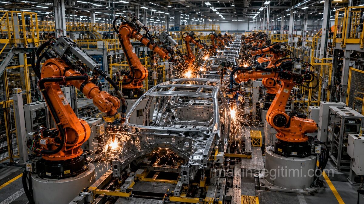
A body welding line is typically divided into four main sub-sections: underbody, side frame, framing/marriage, and final respot welds. Each section takes the part from the previous station, completes a defined set of welds, and hands it off to the next station.
This linear flow is usually supported by buffer areas between stations so the whole line isn’t affected by a delay at any single station. The side frame line is the most complex section of the body and hosts the most robots; a single side frame station can have 8-15 welding robots operating simultaneously.
Cycle Time Targets
An assembly line’s production capacity is determined by the cycle time of its slowest station (the bottleneck); this is why welding cells are designed to match the line’s takt time exactly.
In a high-volume passenger car plant, typical takt time falls in the 45-90 second range; within that window, a welding robot must repeat the cycle of reaching a point, closing the electrodes, applying current (usually 100-300 milliseconds), and moving to the next point 20-40 times in succession.
To meet this target, robot arms run on optimized motion programs that calculate the shortest path, and movements within the cell are synchronized to millisecond precision to prevent collisions between neighboring robots.
Robot Cell Layout
Linear and Cellular Layouts
In high-volume production, the most common approach is the “linear transfer line” layout; the body moves along a conveyor or skid carrier between fixed stations, and at each station robots complete a predefined set of welds.

In more flexible, low-to-medium volume production, a “cellular” layout is preferred instead; here several robots are positioned around a rotary table or turntable, and the same cell can process different body variants in sequence. A cellular layout offers flexibility for model changeovers, while a linear line offers higher raw capacity.
Fixture (Jig) Systems
At the heart of every welding cell are fixtures that hold body panels in place with millimeter-level precision (typically ±0.1-0.3 mm tolerance) during welding. Plants running multi-model production use “flexible fixture” systems that can quickly changeover for different vehicle models; on command from a higher-level control software, these systems reconfigure within seconds to accommodate different body geometries.
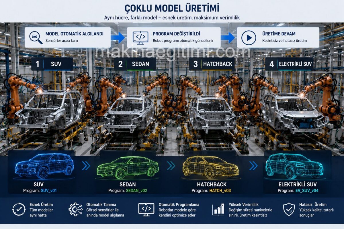
Fixture precision has a direct effect on final weld quality; a misaligned part leads to an incorrectly placed weld point even if the robot itself is programmed correctly.
Weld Quality Inspection
A weld point that looks fine on the surface doesn’t necessarily mean it is mechanically sound; for this reason, modern lines use a multi-layered quality inspection system:
- In-process monitoring: Current, voltage, and electrode force are continuously measured during welding; any value that falls outside the expected range is immediately flagged as a defect.
- Ultrasonic testing: The internal structure of sample-selected weld points is checked non-destructively with sound waves, verifying nugget diameter.
- Peel test: Sample parts pulled from the line at regular intervals are physically torn apart to verify weld nugget diameter and strength; this is an off-line laboratory test.
- Machine vision: Cameras automatically inspect weld point position and surface quality (defects such as spatter, burn-through, or perforation) on every part.
When a weld point is flagged as “suspect,” the line generally does not stop; instead the part is routed to a dedicated rework station, where an additional weld point is added to close the strength gap. This approach prevents a single faulty point from halting the entire production line.
Number of Welding Robots
A modern body assembly line can deploy over 100 welding robots per vehicle body, completing thousands of spot welds.
Spot Weld Duration
A single resistance spot weld operation typically takes 100-300 milliseconds, suiting high-speed production lines.
Laser Welding Speed
Laser welding can proceed much faster than traditional spot welding, reaching speeds of several meters per second.
Spot Welding and Laser Welding on the Line
Resistance spot welding forms the backbone of body welding, with each point completed in 100-300 milliseconds; however, laser welding (or remote laser welding) is increasingly used in visible, aesthetically critical areas such as the roof-to-side-panel joint.
Laser welding allows a single robot arm to weld dozens of points within seconds from a fixed distance (typically 20-50 cm) using a mirror system, without ever touching the part (remote laser welding); this both shortens cycle time and produces a thinner, continuous weld seam that increases body rigidity. However, the upfront investment cost of laser systems is significantly higher than that of spot welding robots.
Comparing Welding Methods
| Feature | Resistance Spot Welding | Remote Laser Welding |
|---|---|---|
| Time per point | 100-300 ms | Few ms (contactless, multi-point) |
| Contact requirement | Electrode makes contact | Contactless |
| Weld seam appearance | Point by point | Continuous, thin line |
| Investment cost | Moderate | High |
| Typical use area | Widespread across the body | Visible/aesthetic areas |
Preventing Line Stoppages: Maintenance and Redundancy Strategies
On a heavily automated line, an unexpected failure in a single robot can halt the entire production flow, which is why plants invest heavily in preventive maintenance and real-time condition monitoring strategies.
Due to wear, electrode tips are typically automatically renewed via “tip dressing” every 100-500 weld points; this is performed automatically by the robot arm without slowing the line. Keeping a redundant robot or a parallel second cell at critical stations is also a common engineering practice that prevents production from stopping entirely in the event of a failure.
Additional Challenges from Mixed Materials
To meet weight reduction targets, modern bodies combine steel, aluminum, and advanced/ultra-high-strength steel (AHSS/UHSS) types together; this “multi-material” approach significantly complicates welding line design.
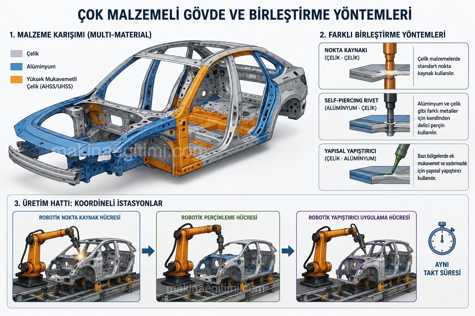
Aluminum has much higher electrical conductivity than steel and requires different current/pressure parameters for spot welding; since two dissimilar metals cannot be joined directly by spot welding, alternative joining methods such as self-piercing rivets or structural adhesive are typically used in these areas instead.
As a result, in a multi-material body line, robotic welding cells must be coordinated together with robotic riveting and adhesive application cells within the same station, all fitting the same takt time.
Line Commissioning with Digital Twins and Simulation
Before a new welding line is physically built, engineers typically model the entire cell virtually as a “digital twin” and use simulation software to test robot trajectories, cycle times, and potential collision points.
This upfront simulation significantly reduces errors that could otherwise emerge during actual commissioning, and helps shorten a new vehicle’s time-to-production (typically on the order of several months).
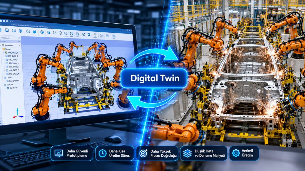
During commissioning, robots are first tested at low speed with empty cycles, then gradually brought up to full speed; during this process weld parameters are verified on real body samples, and all of the quality inspection steps described above are tested from start to finish before the line moves into serial production.
This rigorous verification process is critical to guaranteeing that a line can produce high-quality, consistent bodies from the very first day it enters serial production; a step skipped during commissioning can turn into a systematic error affecting thousands of parts once serial production begins.
Frequently Asked Questions
A typical passenger car body has between 3,000 and 5,000 spot welds; this number varies with vehicle size and body design.
Takt time is the interval between two successive bodies leaving a station on a production line; in high-volume plants it is typically around 45-90 seconds.
Usually not; thanks to redundant robots and buffer areas at critical stations, production can continue at reduced capacity while the faulty robot is repaired.
In-process current/voltage monitoring, ultrasonic testing, machine vision, and sample-based peel tests are used together to inspect weld quality in multiple layers.
Not for now; due to its high cost, laser welding is generally used in areas critical to aesthetics and rigidity, while spot welding remains widespread across the body.
They let the same line produce different vehicle models; by reconfiguring within seconds, they give multi-model production the flexibility it needs.
Related Posts
 State-of-the-Art High-Efficiency Agricultural Machinery
 Anti-Pinch Electric Vehicle Windows
 The Best Dash Cams of 2026: Tested Picks for Every Budget
 Hyundai IVT – Intelligent Variable Transmission Technology
 Features and Advantages of LED Headlights
 Fuel Cell Electric Vehicles (FCEV)
 MEGA MACHINES – 4100 AC Walkthrough
 Bi-Xenon Headlights and Their Advantages