

Definition: The process where a properly ground tool advances along the length of a rotating workpiece, cutting a continuous groove and, by that same motion, leaving ridges of a specific cross-section on the cylindrical part’s surface, is called thread cutting on a lathe.
Metric and Whitworth Thread Systems and Their Elements
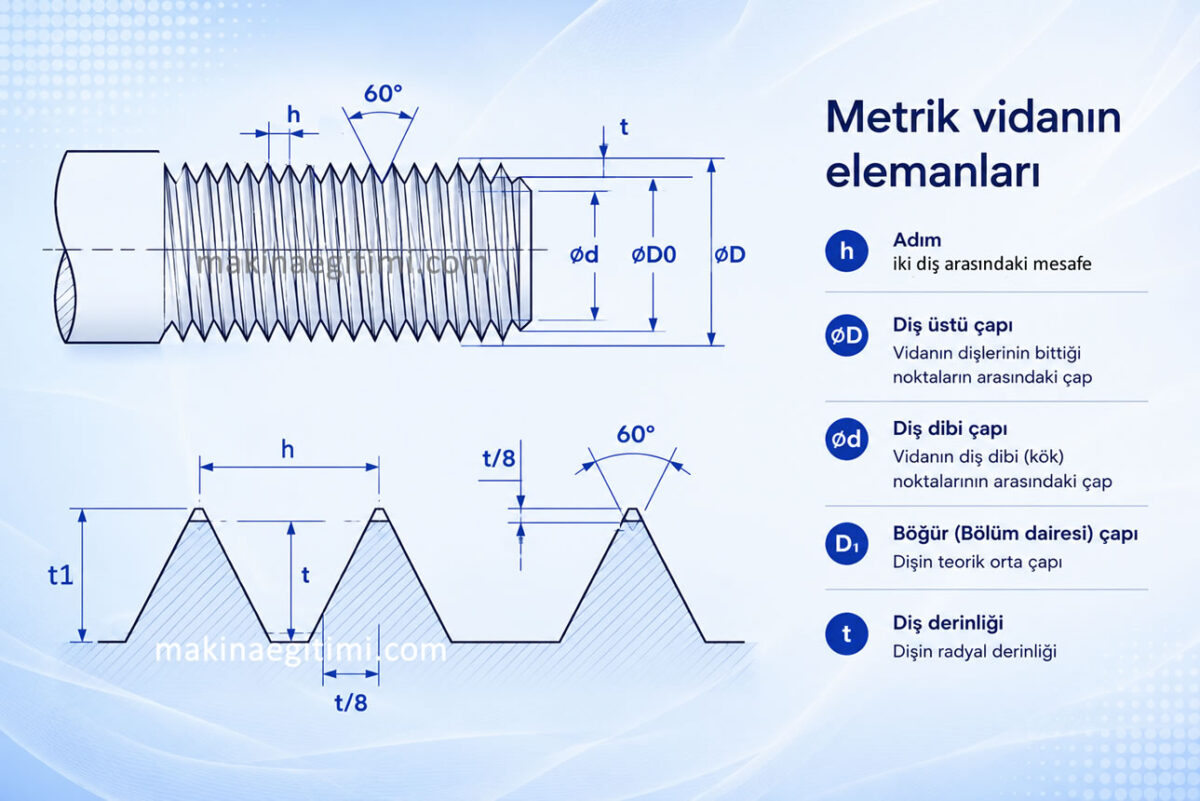
Thread pitch is the axial distance between two consecutive thread crests. On metric threads it is expressed in millimeters (mm). For example, on an M20×2.5 thread, the pitch is 2.5 mm.
Metric Thread System
All dimensions are in mm.
Thread angle = 60o.
Threads are truncated from both crest and root by 1/8 of the thread height.
Approximate thread depth is t = 0.7 x h mm.
Actual thread depths are taken from tables according to the thread’s grade and precision, in order to achieve the correct pitch diameter.
Whitworth Thread System
Diameters are given in the inch unit.
One inch = 25.4 mm.
Thread pitch is given as the number of threads per inch.
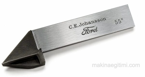
Thread angle is 55°.
Pitch –> p = 25.4 / z
Note: When cutting Whitworth threads, the lathe’s leadscrew setting is based on the number of threads per inch.

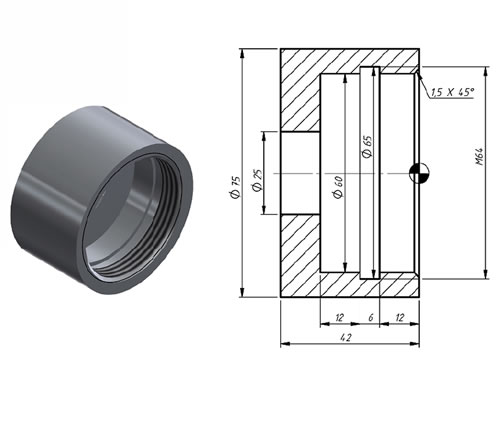
Threading Tool Angle
Metric threading tools standardly have a 60-degree included angle.
Taking Chips in Stages
In thread cutting, the full thread depth is reached not in one pass, but across several staged passes.
Pitch Setting
On a lathe, thread pitch is set through the gearbox ratios between the spindle and the carriage.
Steps for Cutting a Thread on a Lathe
The thread’s depth is calculated. The tool is ground as needed, and its point angle is checked with a thread gauge. The tool height is carefully set relative to the work axis.
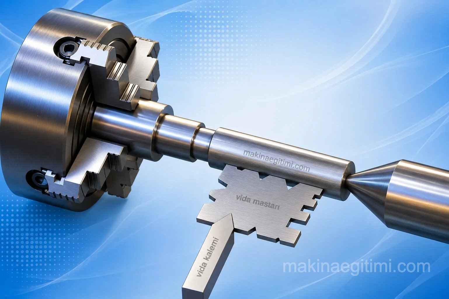
The tool tip’s axis is set with the gauge so that it forms a 90-degree angle with the work axis. (image above)
The lathe’s headstock gearbox is set to give the required thread pitch.

The threading tool is advanced until it just touches the work surface. In this position, the cross-slide micrometer collar is set to zero. The tool is moved to the start of the work. (image above)
After engaging the half-nut lever, the lathe is started. Once the tool begins moving along the work, a shallow trial cut is taken. The trial cut is continued until a few threads are clearly visible.
The tool is withdrawn and the lathe is stopped. Any error is checked with a thread gauge (screw pitch gauge).
The threading tool is brought back to the starting point, slightly beyond the end of the work. For this, if the thread length is short, the spindle is reversed; if the thread length is long, a thread dial indicator is used.
When the end of the thread is reached, the tool is withdrawn by reversing the cross-slide handle.
While withdrawing the tool to return the carriage to the starting position, the spindle must be reversed.
The tool is advanced and another cut is taken. This is repeated until the thread reaches the required depth.
To ensure smooth surfaces, a pass of 0.1 or less (a “spring pass”) is taken. The spring pass can be repeated 2–3 times. Using cutting oil while threading on a lathe helps produce a clean thread; for this, cutting oil should be applied while cutting, or cutting fluid should be dripped from an oil can.

The threads are checked with a test nut or a thread gauge.
Note: If the half-nut lever disengages from the leadscrew for any reason, re-engage the half-nut lever and use the compound and cross slides to reset the tool into the thread groove.
Frequently Asked Questions About Thread Cutting on a Lathe
Related Questions
Because the metric system uses the millimeter as its unit, pitch is given directly in millimeters. Because the Whitworth system is inch-based, pitch is expressed as the number of threads per inch.
A fully sharp thread tip breaks or deforms easily and doesn’t seat properly against the mating thread. Truncating the crest and root by a set amount makes the thread both more durable and gives it better contact with the nut.
Related Posts
 Hand Tools – Types of Wrenches
  Parts of a Lathe, Illustrated
  Operations Performed on a Lathe
  What Is Honing? How Is It Done? Where Is It Used?
  Off-Center (Eccentric) Turning
  Types of Inspection Equipment and Their Use
  What Is a Tool Holder. What Does It Do. How Is It Used?
  Johnson Gauge Blocks (Johansson Gauge Blocks) and Their Use