

Example 1 – Motion Transmission Through Flanges
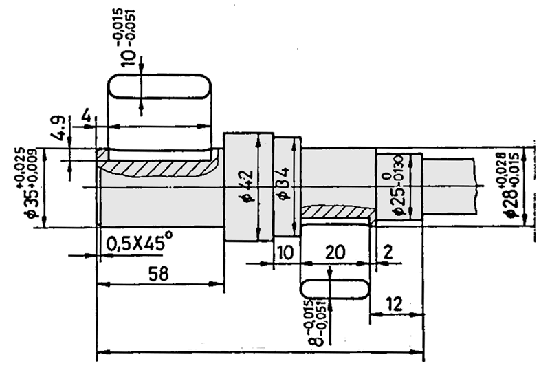
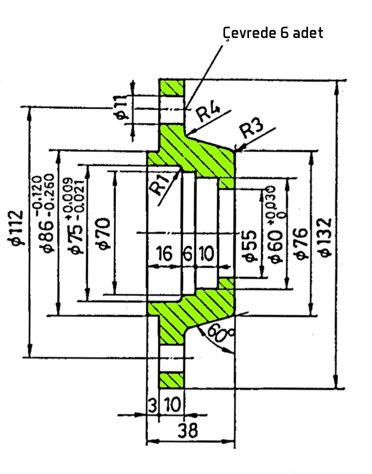
Two shafts are joined by flanges to transmit motion from one shaft to the other (the flanges are shown in green and blue.)
The flanges are fastened to the shafts with a key and a bolt-and-nut. They are joined to each other by a male-female fit. The green one has a recess, the blue one has a matching protrusion.
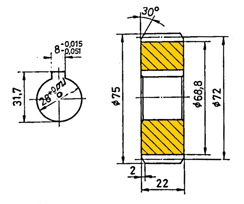
A gear (orange), keyed onto the stepped shaft (Shaft 2) and located axially by a spacer collar (yellow), is also present.

In the example, the tolerance grades are first determined according to the type of fit, and the upper and lower deviations corresponding to each grade are written numerically in their place on the detail drawings.

- Flange 1 – Shaft 1 = Close-fit transition fit (H7/k6)
- Flange 1 – Flange 2 = (male-female flanges) Medium-fit clearance fit (H8/c11)
- Flange 1 keyway width = P9 (per TS 147)
- Flange 2 – Shaft 2 = Close-fit press fit (H7/m6)
- Flange 2 and gear keyway width = P9 (per TS 147)
- Gear – Shaft 2 = Close-fit tight fit (H7/n6)
- Keyway widths on the shaft = P9 (per TS 147)
- Spacer collar – Shaft 2 = (shown in yellow) Coarse-fit coarse clearance fit-1 (H11/h11)



Dimensional Tolerance
In technical drawing, tolerance refers to the difference between the largest and smallest values a dimension is allowed to have.
IT Quality Grades
The ISO tolerance system standardizes the level of precision with quality grades ranging from IT01 to IT18.
Fit Tolerances
In supported shaft-hub connections, whether the fit is a clearance, transition, or interference fit is determined by how the tolerances are positioned relative to each other.
Example 2 – Assembly Drawing of a Pulley Mounted on a Supported Shaft
A belt pulley assembled onto a supported stepped shaft. Parts used in the assembly: bearing, oil seal, washer, hex nut, bolt, castellated nut, cotter pin, key.
- Cover – Housing =
Medium-fit clearance fit (H8 / d10) - Cover – Bearing =
K7 (from the bearing catalog) - Shaft – Bearing =
k6 (from the bearing catalog) - Oil seal bore =
H7 (from the oil seal catalog) - Pulley – Shaft =
Close-fit transition fit (H7 / k6) - Pulley keyway width =
Js9 (per TS 147) - Shaft keyway width = N9 (per TS 147)




Related Questions
The uppercase letter (H) indicates the hole’s tolerance class, and the lowercase letter (k) indicates the shaft’s tolerance class; the numbers indicate how precise that class is. This combination defines how tightly the two parts will fit together.
This depends on the part’s function. A part that transmits torque, like a gear, needs a tight fit to the shaft, while a collar that needs to be removed and reinstalled is designed with a looser fit.
Related Posts
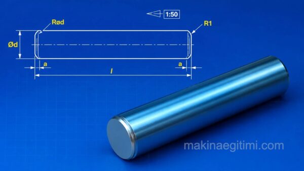 Pins and Pinned Joint Technical Drawings
 Couplings and Coupling Drawings in Technical Drawing
 Hex Nut and Washer Drawing Exercise
 Spur Gear Technical Drawings
 Vise Technical Drawing – Assembly and Detail Manufacturing Drawing
 Washer Die Assembly and Detail Drawings – Dwg pdf
 Pivot Pins – What Is a Pivot Pin, Where Is It Used
 Standard Representation and Dimensions of a Washer